A riveting device and method based on frequency conversion motor to control riveting head trajectory

A variable frequency motor and trajectory technology, applied in the direction of AC motor control, control system, electrical components, etc., can solve the problems of non-adjustable control, life concentration, difficulty in guaranteeing energy saving and emission reduction, and large energy consumption, so as to achieve energy consumption and use The effect of life optimization, simple and easy technical means, and reduced scrap rate

Inactive Publication Date: 2016-05-04
SOUTH CHINA UNIV OF TECH
View PDF6 Cites 0 Cited by
  • Summary
  • Abstract
  • Description
  • Claims
  • Application Information

AI Technical Summary

Problems solved by technology

[0004] As the main axial riveting technology, the most commonly used riveting head trajectory in the existing radial riveting technology is the quincunx trajectory movement. During the riveting process of the riveting equipment, the movement trajectory of the riveting head is often fixed and cannot be adjusted and controlled. Without an optimized motion track, this will lead to the fact that the axial preload of the assembled bearing unit cannot meet the requirements or the phenomenon that the required axial preload has been reached but the energy consumption is too large, which seriously affects the performance of shaft riveting. Reliability and stability of bearing unit quality, life concentration and energy saving and emission reduction are difficult to guarantee

Method used


Image

  • A riveting device and method based on frequency conversion motor to control riveting head trajectory
  • A riveting device and method based on frequency conversion motor to control riveting head trajectory
  • A riveting device and method based on frequency conversion motor to control riveting head trajectory

Examples


Embodiment

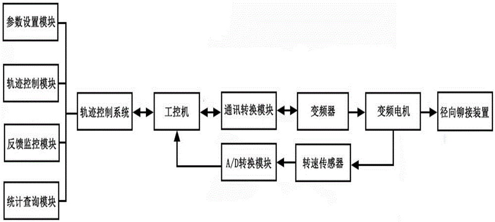
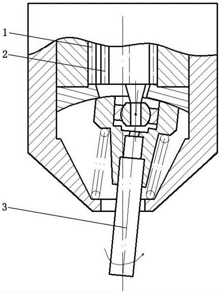
[0042] Such as Figure 1 to Figure 4 shown. The present invention is a riveting device for controlling the trajectory of a riveting head based on a frequency conversion motor, comprising a trajectory control system, an industrial computer, a communication conversion module, a frequency converter, a frequency conversion motor, and a radial riveting device connected in sequence;

[0043] The frequency conversion motor is connected to the industrial computer through the speed sensor and the A / D conversion module to form a closed-loop feedback control system.

[0044] The speed sensor is a voltage output sensor, which is installed on the output shaft end of the variable frequency motor, and converts the speed signal of the motor into a voltage signal, which is transmitted to the industrial computer through the data acquisition module, and the speed signal is calculated by the running state monitoring module in the trajectory control system analyze.

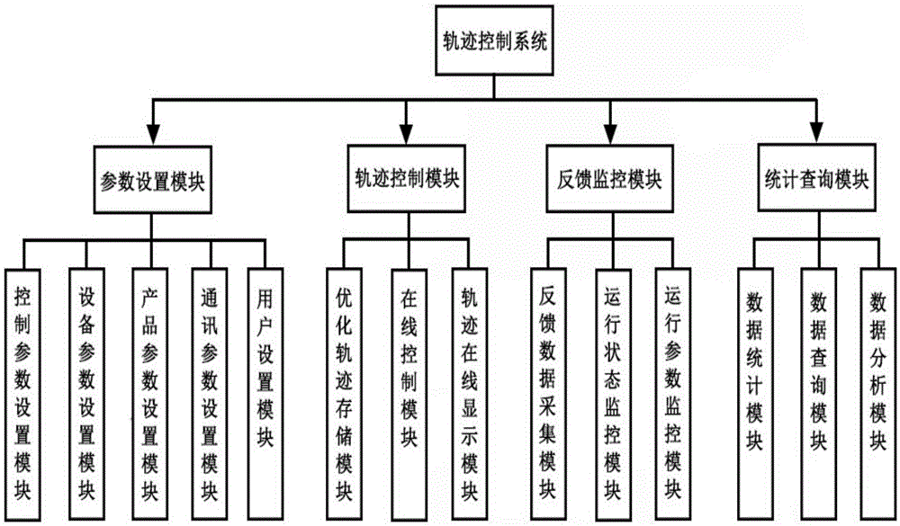
[0045] The trajectory contro...


PUM


Abstract

The invention discloses a riveting device and a riveting method for controlling the trajectory of a rivet head based on a variable frequency motor. The riveting device comprises a trajectory control system, an industrial personal computer, a communication conversion module, a frequency converter, the variable frequency motor and a radial riveting device, all of which are orderly connected together; the variable frequency motor is connected with the industrial control machine by use of a rotating speed sensor and an A / D conversion module to form a closed-loop feedback control system; the rotating speed sensor is a voltage output sensor which is mounted at the output shaft end of the variable frequency motor; the rotating speed signal of the motor is converted into a voltage signal which is transmitted to the industrial personal computer by use of a data acquisition module, and the rotating speed signal is computationally analyzed by an operating state monitoring module in the trajectory control system. The riveting device for controlling the trajectory of the rivet head based on the variable frequency motor, the axial pretightening force of the rivet head and the shaft end of a flange plate hub is controlled by selecting the optimized rivet head trajectory so that the energy consumption and the service life of an assembled bearing unit can be optimized under the premise of satisfying the axial pretightening force, and therefore, the reliability of shaft riveting and the stability of the quality of the bearing unit are improved and the development requirements on energy conservation and emission reduction are met.

Description

technical field [0001] The invention relates to electric riveting equipment and a riveting process of a shaft riveting hub bearing unit, in particular to a riveting device and method based on a variable frequency motor to control the trajectory of a riveting head. Background technique [0002] As one of the key components of automobiles, hub bearings need to bear combined radial and axial loads during work. Traditional automobile wheel bearings are installed on the car wheel shaft in pairs by using two sets of independent angular contact ball bearings or tapered roller bearings. Therefore, a series of processes such as bearing clearance adjustment, preload, oiling and greasing, and sealing are required. , due to many human control factors, the bearing assembly of this structure will inevitably lead to difficult assembly, long assembly cycle, high cost, poor reliability and other problems, and it is difficult to adapt to the fierce market competition. [0003] In recent year...

Claims


Application Information

Patent Timeline
Patent Type & Authority Patents(China)
IPC IPC(8): B21D39/00H02P27/04
CPCB21D39/00H02P27/04Y02P70/10
Inventor 曲杰张国杰许华忠
Owner SOUTH CHINA UNIV OF TECH
Why Eureka
Try Eureka