
Rotary tool-feeding cutting mechanism for lathe

A technology of cutting mechanism and rotary feed, which is applied to metal processing machinery parts, metal processing equipment, feeding devices, etc., can solve the problems of high processing efficiency, safety and reliability, low processing and manufacturing costs, and achieve low manufacturing costs, High processing efficiency, high safety and reliability

Inactive Publication Date: 2015-03-11
LINYI JINXING MACHINE TOOL
View PDF8 Cites 0 Cited by
  • Summary
  • Abstract
  • Description
  • Claims
  • Application Information

AI Technical Summary

Problems solved by technology

[0003] The purpose of the present invention is to provide a rotary feed cutting mechanism for lathes, which can solve the problem that some workpieces need to be processed after the tool is rotated and then fed into the processing position, and the processing efficiency and safety reliability are high. low manufacturing cost

Method used


Image

  • Rotary tool-feeding cutting mechanism for lathe
  • Rotary tool-feeding cutting mechanism for lathe

Examples


Embodiment 1

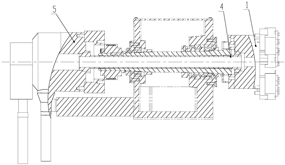
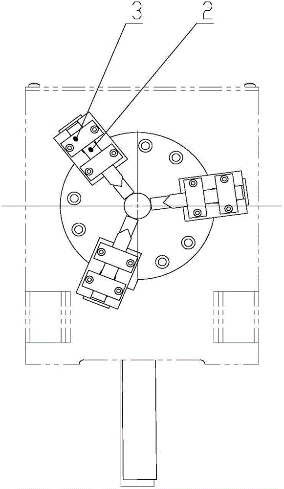
[0017] Embodiment 1: A rotary feed cutting mechanism for a lathe, including a control mechanism, the control mechanism is connected to a power unit 5, and the power unit 5 is connected to the chuck 1 through a connecting rod 4, and the chuck 1 of the chuck 1 The claw is provided with a cutting mechanism; the control mechanism includes a foot switch and a solenoid valve, the foot switch is connected to the solenoid valve, and the solenoid valve is connected to the power device; the power device 5 is a rotary cylinder; the cutting mechanism includes three The tool 2 located on the same plane, the tool 2 is installed on the claw of the chuck 1 through the pressing blade 3; the chuck 1 is a pneumatic chuck.

Embodiment 2

[0018] Embodiment 2: A rotary feed cutting mechanism for a lathe, including a control mechanism, the control mechanism is connected to the power unit 5, the power unit 5 is connected to the chuck 1 through the connecting rod 4, and the chuck 1 of the chuck 1 The claw is provided with a cutting mechanism; the control mechanism includes a foot switch and a solenoid valve, the foot switch is connected to the solenoid valve, and the solenoid valve is connected to the power device; the power device 5 is a rotary oil cylinder; the cutting mechanism includes three The tool 2 is located on the same plane, and the tool 2 is installed on the claw of the chuck 1 through the pressing blade 3; the chuck 1 is a hydraulic chuck.

[0019] When the present invention is used to cut the workpiece, the chuck 1 is first in the open position, and the claws on the chuck 1 drive the tool 2 to move outward together. After the workpiece moves to the processing position of the claws, step on the foot swi...


PUM


Abstract

The invention discloses a rotary tool-feeding cutting mechanism for a lathe and belongs to a turning mechanism with a tool performing radial motion. The rotary tool-feeding cutting mechanism is used for workpiece machining and comprises a control mechanism, wherein the control mechanism is connected with a power device, the power device is connected with chuck though a connecting rod, and a cutting mechanism is arranged on a clamping claw of the chuck. By means of the technical scheme, the problem that machining can be performed through tool rotation and tool feeding after a part of workpiece is fed to a machining position can be solved, the machining efficiency and safety reliability are high, and the machining and manufacturing cost is low.

Description

technical field [0001] The invention belongs to a turning mechanism for a radially moving tool, in particular to a rotary feed cutting mechanism for a lathe. Background technique [0002] During the turning process of parts, some workpieces can neither be rotated nor processed from the end face of the station, but the tool is only allowed to cut from the middle of the workpiece, that is, after the workpiece needs to be fed to the processing station The tool rotates and then feeds. The existing solution is to use the elastic deformation of the tool bar or the method of U-axis feeding. Using the elastic deformation of the tool bar, the manual feeding method is used, which has low efficiency and poor safety and reliability. Workers are required to have enough Proficiency and high operating experience; if U-axis feed is used, the cost of machining will increase, and the output is not directly proportional to the cost in mass production. Contents of the invention [0003] The...

Claims


Application Information

Patent Timeline
Patent Type & Authority Applications(China)
IPC IPC(8): B23Q5/22
CPCB23Q5/22B23Q2705/102
Inventor 王文剑姜超陈学军
Owner LINYI JINXING MACHINE TOOL
Learn More