Speed-regulation clutch

A clutch and speed regulation technology, applied in the direction of machine/engine, coolant flow control, engine components, etc., can solve the problems of short life, heavy machine wear, low work efficiency, etc., to prolong the service life, save energy, and facilitate The effect of dismantling and repairing

Active Publication Date: 2015-03-11
LONGKOU ZHONGYU AUTOMOBILE FAN CLUTCH
View PDF6 Cites 0 Cited by
  • Summary
  • Abstract
  • Description
  • Claims
  • Application Information

AI Technical Summary

Problems solved by technology

[0003] The purpose of the invention of this application is to solve the technical problems of large machine wear, short life and low work efficiency caused by the current equipment constantly rotating at the same speed as the pulley during the working process, and to provide a device that can adjust the speed of the equipment, save energy, Overdrive clutches that reduce machine wear and increase machine efficiency

Method used


Image

  • Speed-regulation clutch
  • Speed-regulation clutch
  • Speed-regulation clutch

Examples


Embodiment 1

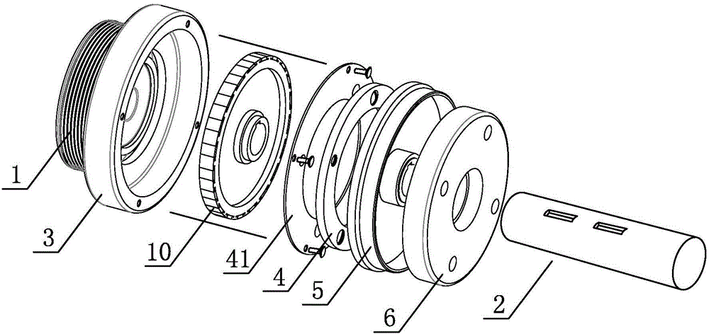
[0025] Such as figure 1 and 3 As shown, the speed regulating clutch of this embodiment is used to transmit the power of the pulley 1 to the power input shaft 2 of the equipment, the connection hole of the pulley 1 is sleeved on the front end of the power input shaft 2 through a bearing, and the pulley 1 faces one side of the equipment It is the right side of the belt pulley 1, the fixed disk 3 is installed on the right side, the fixed disk 3 is fixedly connected with the pulley 1 with bolts, the right side of the fixed disk 3 has a groove, the inside of the groove accommodates the magnet disk 10, the magnet disk 10 Fixed on the power input shaft 2 by a flat key, the magnet disc 10 can rotate in the groove along with the power input shaft 2, and the groove side of the groove is fixedly connected to the suction disc 4 through the spring piece 41, which has two inner and outer circles Screw holes, the screw holes of the outer ring are used to thread the spring sheet 41 and the f...

Embodiment 2

[0031] Such as Figure 4-5As shown, the difference between this embodiment and Embodiment 1 is that there is an installation groove 51-1 in the cavity on the right side of the transmission disc 5-1, the installation groove 51-1 is an annular groove, and a second spring is installed inside it. The sheet 91-1 and the second suction plate 9-1, the second spring sheet 91-1 has two rings of screw holes inside and outside, and the inner ring screw holes are used to screw the second spring sheet 91-1 and the installation groove 51-1, The screw holes in the outer ring are used to bolt the second spring piece 91-1 and the second suction plate 9-1, and the second coil 8 facing the second suction plate 9-1 is also arranged in the iron core 6-1. -1, when the second coil 8-1 is energized, a magnetic field is generated, which can attract the second engaging disk 9-1 to the iron core 6-1.

[0032] The control method of the speed regulating clutch in this embodiment for three-speed equipment...

Embodiment 3

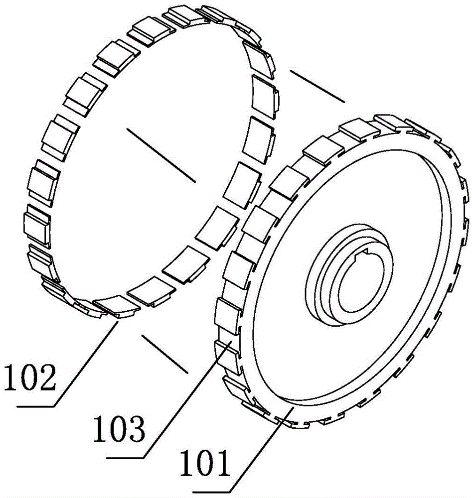
[0037] Such as Figure 6-7 As shown, the difference between the present embodiment and the first embodiment is that the fixed magnet disk 101-2 is installed on the power input shaft 2-2 through a bearing, and the second spring piece 91 is arranged on the right side of the fixed magnet disk 101-2. -2 and the second suction plate 9-2, the second spring piece 91-2 has two circles of screw holes inside and outside, and the outer ring screw holes are used to thread the second spring piece 91-2 and the magnet fixing plate 101-2, the inner The ring screw hole is used for bolting the second spring piece 91-2 and the second suction disk 9-2, and the second coil 8-2 facing the second suction disk 9-2 is also provided in the iron core 6-2. 2.

[0038] The control method of the speed regulating clutch in this embodiment for three-speed equipment is as follows: start the motor driving the pulley 1-2, and then control the speed regulating clutch according to the speed requirement of the eq...


PUM


Abstract

The invention provides a speed-regulation clutch, which comprises a belt pulley, a power input shaft sheathed in a connecting hole of the belt pulley, a fixed disc fixedly arranged on the outer side surface of the belt pulley, a large sucking disc connected with the fixed disc, a driving disc fixedly arranged on the power input shaft by virtue of a flat key and an iron core fixedly arranged relative to the power input shaft, wherein the side surface of the driving disc is provided with a cavity; the iron core is accommodated in the cavity and is internally provided with a coil opposite to the sucking disc; the fixed disc is also provided with a groove in which a magnet disc is arranged; the magnet disc is arranged on the power input shaft; multiple permanent magnet fixing discs are uniformly distributed on the periphery of the magnet disc and are internally provided with annular soft magnets opposite to the permanent magnets; when the coil is powered on, the sucking disc compresses the driving disc under the effect of a magnetic field; when the coil is powered off, the sucking disc is separated from the driving disc under the effect of a leaf spring. The speed-regulation clutch can be used for regulating the speed of equipment, saving energy sources, reducing machine abrasion and improving the machine working efficiency.

Description

technical field [0001] The invention relates to a water cooling system for an engine, in particular to a speed regulating device with different rotational speeds controlled by an electromagnetic clutch. Background technique [0002] The working principle of the existing equipment is: the engine drives the power input shaft and the impeller of the equipment to rotate through the pulley, the coolant in the equipment is driven by the impeller to rotate together, and is thrown to the edge of the equipment shell under the action of centrifugal force, and a certain pressure is generated at the same time , and then flow out from the water outlet or water pipe, and the pressure at the center of the impeller decreases due to the coolant being thrown out, and the coolant in the water tank is sucked into the impeller through the water pipe under the action of the pressure difference between the equipment inlet and the center of the impeller to realize the cooling of the coolant recipro...

Claims


Application Information

Patent Timeline
Patent Type & Authority Applications(China)
IPC IPC(8): F01P7/14F01P5/12
Inventor 王兆宇陈晓亮王策
Owner LONGKOU ZHONGYU AUTOMOBILE FAN CLUTCH
Why Eureka
Try Eureka