Critical load calculation method of parallel-shaft tooth-typed compressor

A critical load and calculation method technology, applied in the direction of machines/engines, etc., can solve problems such as abnormal unit vibration, car jumping, forced production stop, etc.

Active Publication Date: 2015-03-11
BEIJING UNIV OF CHEM TECH
View PDF4 Cites 4 Cited by
  • Summary
  • Abstract
  • Description
  • Claims
  • Application Information

AI Technical Summary

Problems solved by technology

[0003] The critical load fault is a fault of excessive vibration caused by the change of the operating conditions of the parallel shaft gear compressor. The change of the aerodynamic load due to the change of the inlet guide vane of the compressor affects the change of the rigidity of the compressed gas working rotor support bearing. , and the change of the bearing stiffness will affect the change of the critical speed of the rotor at each stage. When the critical speed of a certain stage coincides with the rated speed during the stiffness change process, resonance will be caused, resulting in abnormal vibration of the unit. Once the vibration is too large, it will Caused a car jump, resulting in the production being forced to stop

Method used


Image

  • Critical load calculation method of parallel-shaft tooth-typed compressor
  • Critical load calculation method of parallel-shaft tooth-typed compressor
  • Critical load calculation method of parallel-shaft tooth-typed compressor

Examples


Embodiment Construction

[0023] The present invention will be described in detail below in conjunction with the accompanying drawings and examples.

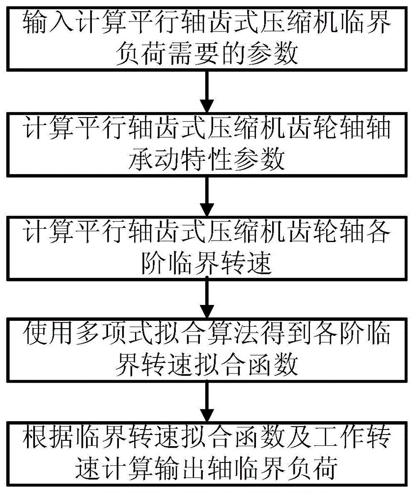
[0024] The flow chart of a method for calculating the critical load of a parallel-shaft gear compressor is as follows: figure 1 As shown, it mainly includes:

[0025] (1) Obtain the parameters of the parallel-shaft gear compressor that needs to calculate the critical load, including: the basic structural dimensions of each shaft of the parallel-shaft gear compressor, the position, mass, diameter moment of inertia and pole moment of inertia of each impeller, each gear The normal operating speed of the shaft, the installation angle of each gear, the installation position information of the gear, the diameter of the pitch circle, the helix angle and the pressure angle, and the rated operating power;

[0026] (2) According to the gear installation position of the gear shaft, pitch circle diameter, helix angle, pressure angle and rated operating power, calcu...


PUM


Abstract

A critical load calculation method of parallel-shaft tooth-typed compressor belongs to the field of rotating mechanical rotor dynamics and particularly includes following steps: (1) obtaining required parameters of critical loads of the parallel-shaft tooth-typed compressor; (2) calculating dynamic characteristic parameters of each gear output shaft under different powers according to the obtained parameters; (3) inputting the dynamic characteristic parameters into a dynamic equation and calculating a first-stage critical rotating speed, a second-stage critical rotating speed and a third-stage critical rotating speed of each gear output shaft under different powers through a transfer matrix method; (4) fitting the first-stage critical rotating speed, the second-stage critical rotating speed and the third-stage critical rotating speed of each gear output shaft under different powers through a polynomial to obtain fitting functions of each critical rotating speed; and (5) according to an operation rotating speed and the critical rotating speed fitting function of each gear output shaft, determining whether a critical rotating speed of each gear output shaft exists or not in design and calculating the particular critical rotating speed. The method is used for determining whether the critical load of each gear output shaft exists or not during design of the parallel-shaft tooth-typed compressor, thereby guiding a designer to optimize design of the compressor.

Description

technical field [0001] The invention belongs to the technical field of rotor dynamics of rotary machines, and relates to a method for calculating the critical load of a parallel shaft gear compressor. Background technique [0002] Due to its high operating efficiency and compact structure, parallel shaft gear compressors are widely used in compressing air and carbon dioxide in process industries such as petroleum and petrochemical industries. During the actual operation on site, it was found that the parallel shaft gear compressor had excessive vibration due to the adjustment of the aerodynamic load when it was running at the rated speed. The fault caused by this problem was the critical load fault. The book Mechanical Fault Diagnosis and Self-healing written by Academician Gao Jinji, an expert in equipment fault diagnosis in my country, discusses and studies critical load faults, and successfully solves the critical load fault of a parallel shaft gear compressor. [0003] ...

Claims


Application Information

Patent Timeline
Patent Type & Authority Applications(China)
IPC IPC(8): F04C28/28
Inventor 江志农张明冯坤马波高金吉
Owner BEIJING UNIV OF CHEM TECH
Why Eureka
Try Eureka