
Hall thruster plume divergence angle measuring method within low-frequency oscillation time scale

A Hall thruster and plume divergence angle technology, which is applied in the direction of measuring devices, machine/structural component testing, instruments, etc., can solve the problem of not being able to obtain the time dynamic change of plume divergence angle on the order of tens of μs, and achieve Avoid the effects of high-speed mobile devices

Active Publication Date: 2015-03-11
HARBIN INST OF TECH
View PDF4 Cites 7 Cited by
  • Summary
  • Abstract
  • Description
  • Claims
  • Application Information

AI Technical Summary

Problems solved by technology

[0004] The purpose of the present invention is to solve the problem that the existing measurement method cannot obtain the dynamic change of the plume divergence angle with time in the order of tens of μs, thereby providing a method for measuring the plume divergence angle within the low-frequency oscillation time scale of the Hall thruster

Method used


Image

  • Hall thruster plume divergence angle measuring method within low-frequency oscillation time scale
  • Hall thruster plume divergence angle measuring method within low-frequency oscillation time scale
  • Hall thruster plume divergence angle measuring method within low-frequency oscillation time scale

Examples


specific Embodiment approach 1

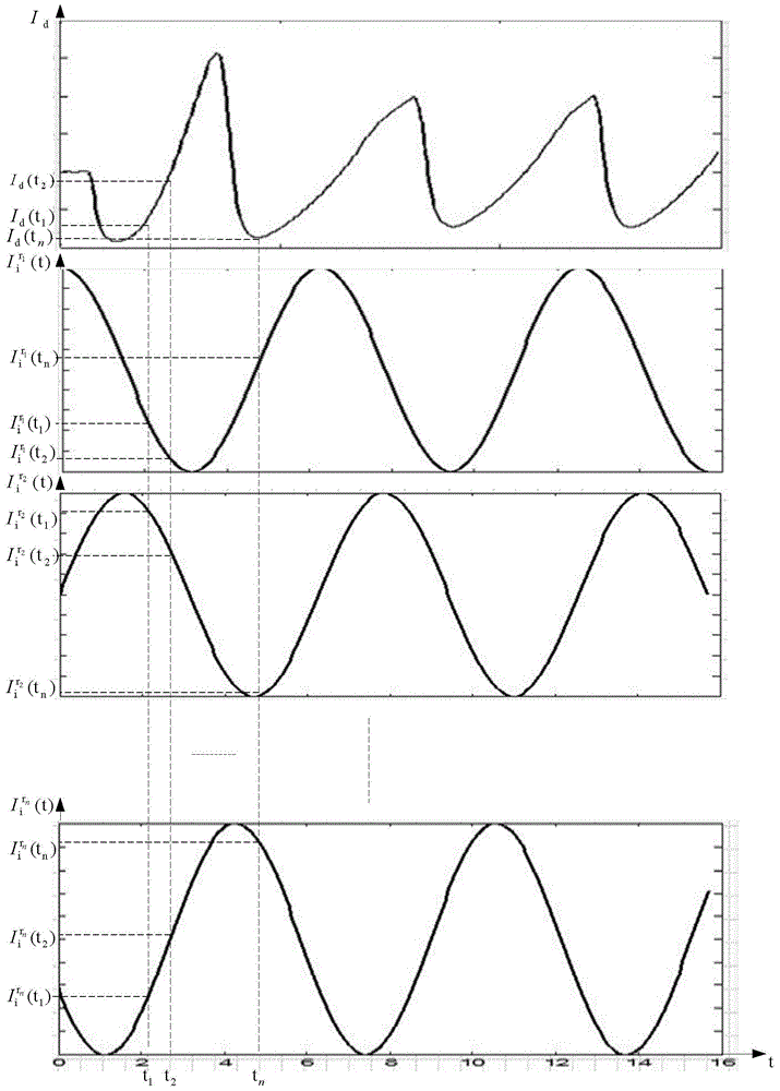
[0018] Embodiment 1. The method for measuring the divergence angle of the plume in the low-frequency oscillation time scale of the Hall thruster, which is realized by the following steps:

[0019] N measuring points are set at the outlet of the Hall thruster; N is an integer greater than 2;

[0020] The N measuring points are located on a straight line, and the straight line is radially distributed along the Hall thruster;

[0021] N measurement points are set at equal intervals; the initial value of r is set to 1;

[0022] Step 1. Install the probe at the rth measurement point, and use the probe to detect the low-frequency oscillating current and ion current of the Hall thruster at the rth measurement point; obtain the Hall thruster at the rth measurement point The curve of low-frequency oscillating current changing with time, and the curve of ion current changing with time;

[0023] Step 2: Add 1 to the value of r, and judge whether the value of r is greater than N, if the...

specific Embodiment approach 2

[0027] Embodiment 2. The difference between this embodiment and the method for measuring the plume divergence angle in the low-frequency oscillation time scale of the Hall thruster described in Embodiment 1 is that the distance between two adjacent measurement points is 0.2 cm.

specific Embodiment approach 3

[0028] Specific Embodiment 3. The difference between this specific embodiment and the method for measuring the plume divergence angle in the low-frequency oscillation time scale of the Hall thruster described in the specific embodiment 1 is that M=0.12.


PUM


Abstract

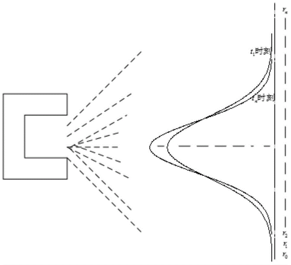
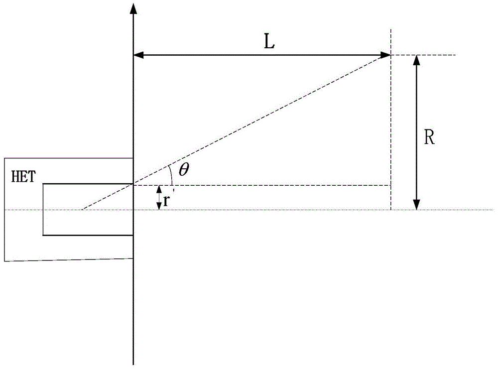
The invention discloses a Hall thruster plume divergence angle measuring method within a low-frequency oscillation time scale, and relates to the field of plasma propulsion, for the purpose of obtaining the dynamic characteristic of the plume divergence angle of a Hall thruster within a low-frequency oscillation time scale. A low-frequency oscillation current oscillogram and an ion current waveform of each measuring point are measured through a probe, a low-frequency oscillation current value at a time point is selected, a point corresponding to the low-frequency oscillation current value is found from an ion current curve, after fitting is performed on the acquired point, a radial ion distribution curve is obtained, the plume divergence angle at the time point is obtained through calculation, and through such a way, a change curve of the plume divergence angle along with time can be obtained. According to the invention, the dynamic characteristic of the plume divergence angle is measured, the change curve of the plume divergence angle within the low-frequency oscillation time scale is obtained, and an effective technical approach is provided for research on the change of the plume divergence angle of the Hall thruster. The Hall thruster plume divergence angle measuring method within the low-frequency oscillation time scale is applied to measurement of the plume divergence angle of the Hall thruster within the low-frequency oscillation time scale.

Description

technical field [0001] The present invention relates to the field of plasma propulsion. Background technique [0002] In recent years, the Hall electric propulsion system has been successfully applied in satellite position maintenance and orbit elevation due to its high efficiency, moderate specific impulse and long life, and has become an important research direction in the field of aerospace propulsion. The plume of the Hall thruster is a high-speed thin plasma and relatively divergent, which pollutes the surface of the spacecraft, solar cells and communication equipment. Therefore, the evaluation and measurement of the divergence angle of the Hall thruster plume is an important part of the study of the Hall thruster. one of the contents. The plume divergence angle of the Hall thruster refers to the beam expansion angle of the ejected plasma in the plume space, so it is usually used to reflect the concentration and focusing characteristics of the plasma beam, and it is al...

Claims


Application Information

Patent Timeline
IPC IPC(8): G01M9/00
Inventor 李婧魏立秋韩亮杨子怡于达仁
Owner HARBIN INST OF TECH
Learn More