
Ultrasonic micro-damage location detection method and device based on collinear aliasing of Lamb waves

A positioning detection and micro-damage technology, which is applied to the analysis of solids using sound waves/ultrasonic waves/infrasonic waves, can solve the problem that the specific location of the damage that cannot be accurately determined by the nonlinear response, the location of the damage that cannot be determined by the nonlinear response, and the influence of the nonlinear Lamb Accuracy of wave detection technology and other issues, to achieve the effect of improving accuracy

Inactive Publication Date: 2015-03-11
XIAMEN UNIV
View PDF4 Cites 14 Cited by
  • Summary
  • Abstract
  • Description
  • Claims
  • Application Information

AI Technical Summary

Problems solved by technology

[0006] 2. Unable to determine the location of the damage causing the nonlinear response
[0007] The nonlinear value measured by the nonlinear Lamb wave technology based on the second-order harmonic method includes the nonlinear value of the entire area from the signal excitation transducer to the signal receiving transducer, so this technology cannot accurately determine the detection area Specific location of damage causing nonlinear response
The nonlinear Lamb wave detection technology based on the second-order harmonic method can only qualitatively estimate the nonlinear change of the material, but cannot accurately determine the damage location. This limitation will affect the accuracy of the nonlinear Lamb wave detection technology

Method used


Image

  • Ultrasonic micro-damage location detection method and device based on collinear aliasing of Lamb waves
  • Ultrasonic micro-damage location detection method and device based on collinear aliasing of Lamb waves

Examples


Embodiment Construction

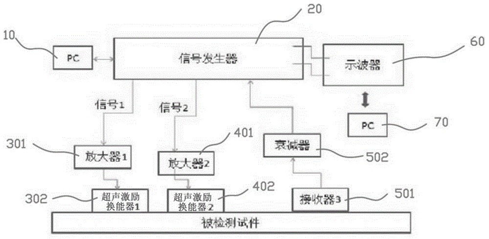
[0032] First, the principle on which the ultrasonic micro-damage location detection method of the present invention is based is briefly explained: the difference frequency and sum frequency harmonics generated after the acoustic beams are aliased are one of the phenomena of acoustic wave nonlinear response. If there is a nonlinear source inside the sample material, two ultrasonic waves of different frequencies propagate in it, and interaction will occur, resulting in difference frequency harmonics and sum frequency harmonics that are different from the initial wave frequencies of the two beams. Because the nonlinear response of beam aliasing only occurs during the propagation of the specimen, this ultrasonic nonlinear phenomenon can only describe the nonlinearity of the propagation medium. This nonlinear detection method breaks through the limitation that the nonlinear Lamb wave detection method based on the second-order harmonic method cannot effectively distinguish the source ...


PUM


Abstract

The invention relates to nondestructive testing, and provides an ultrasonic micro-damage location detection method based on collinear aliasing of Lamb waves. The method comprises the following steps: (A), a pair of Lamb wave mode combinations with different frequency and propagation modes is determined; (B), generated difference frequency harmonic waves of the Lamb waves are determined; (C), the pair of initial Lamb wave modes are excited by signal excitation units; (D), a signal receiving unit having corresponding frequency with the difference frequency harmonic waves is selected to receive the difference frequency harmonic waves; (E), an area where beams start for aliasing is confirmed; (F), positions of two initial excitation sources are changed; (G), scanning detection is performed on a tested object; and (H), the micro-damage location of the tested object is calculated and confirmed according to amplitude change of the difference frequency harmonic waves. The invention further provides an ultrasonic micro-damage location detection device based on the collinear aliasing of the Lamb waves. The device comprises a first computer, a signal generator, a first signal excitation unit, a second signal excitation unit, a signal receiving unit, an oscilloscope and a second computer. The ultrasonic micro-damage location detection method and device are applied to material detection.

Description

Technical field [0001] The present invention relates to non-destructive testing, in particular to ultrasonic testing. Specifically, it is a method for non-destructive evaluation and characterization of micro-damages or micro-defects such as early fatigue damage of materials and early degradation of material properties. It is based on the nonlinearity of Lamb wave collinear aliasing Realized by ultrasound technology. Background technique [0002] For the key load-bearing structural parts of important equipment such as aerospace and nuclear power that have been in service for a long time, the performance degradation of structural materials is inevitable, such as tensile performance degradation, thermal fatigue creep damage, and reduced bond strength. In order to ensure the safe operation of these key structural parts, it is very important to develop technical means for early performance degradation assessment of structural materials. Lamb waves propagating in structural materials ...

Claims


Application Information

Patent Timeline
Patent Type & Authority Applications(China)
IPC IPC(8): G01N29/04
Inventor 李卫彬胡诗诚施展
Owner XIAMEN UNIV
Learn More