Eureka AIR delivers breakthrough ideas for toughest innovation challenges, trusted by R&D personnel around the world.

Ultrasonic Doppler flow direction and flow rate instrument

A flow meter and ultrasonic technology, applied in the field of ultrasonic Doppler flow direction flow meter, can solve the problems of affecting the measurement accuracy, being unable to measure, destroying the natural flow field pattern, etc., achieving accurate sampling data, ensuring measurement accuracy, and convenient and fast measurement Effect

Inactive Publication Date: 2015-03-11
XIAMEN BOYIDA TECH
View PDF5 Cites 3 Cited by
  • Summary
  • Abstract
  • Description
  • Claims
  • Application Information

AI Technical Summary

Problems solved by technology

[0002] At present, the flow measurement of my country's water conservancy and hydrological system mainly uses the traditional mechanical rotor flow meter, because the rotor flow meter relies on the water flow to push the blade (or rotary cup) sensor to rotate, and then converts the number of output pulses according to a certain relationship to obtain the flow rate value. , but when the water flow pushes the sensor to rotate, it also destroys the pattern of the natural flow field, so the flow rate measured by this type of flow meter is not the flow rate value of the natural flow field, which affects the measurement accuracy
When the flow velocity is too small and the thrust is not enough to push the blades to rotate, it cannot be measured, so weak flow cannot be measured
Since the sensor is a rotating part, it is afraid of mud and sand clogging and entanglement of aquatic plants and floating objects, which will affect the measurement accuracy or even make it impossible to measure
Fear of collision, easy deformation, poor measurement linearity

Method used


Image

  • Ultrasonic Doppler flow direction and flow rate instrument
  • Ultrasonic Doppler flow direction and flow rate instrument
  • Ultrasonic Doppler flow direction and flow rate instrument

Examples


Embodiment Construction

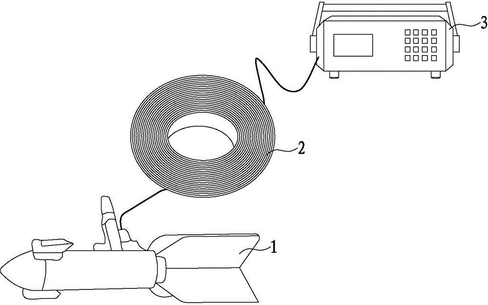
[0022] Such as figure 1 As shown, the present invention is an ultrasonic Doppler flow velocity meter, which is composed of a probe 1, a cable 2, and a water surface host 3.

[0023] The probe 1 is connected with the surface host 3 through the cable 2, and transmits the underwater signal to the surface host 3.

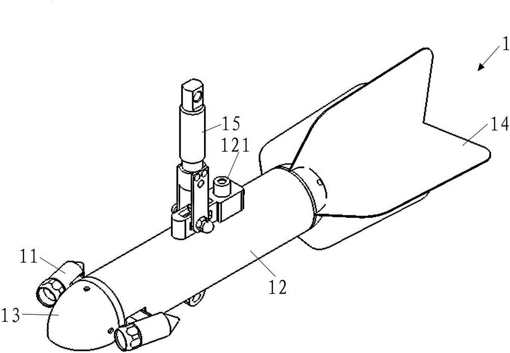
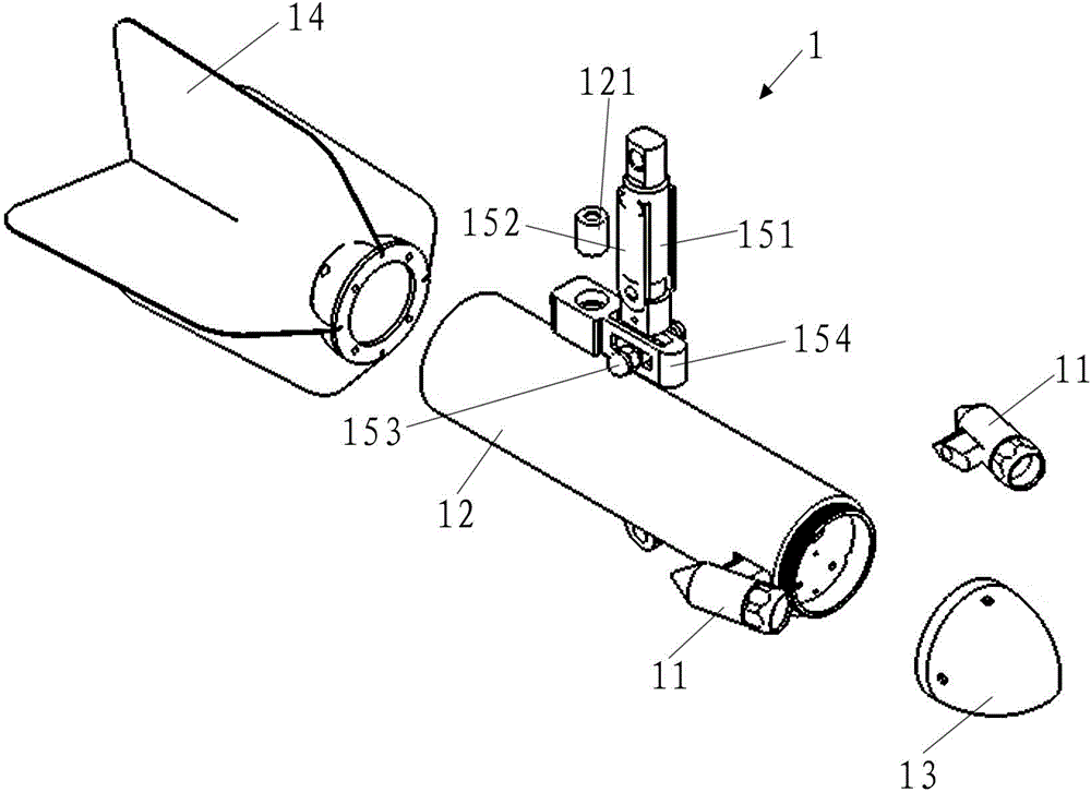
[0024] Such as Figure 2-Figure 7 As shown, the probe 1 includes two transducers 11, a pipe body 12, a diverter head 13, an empennage 14, a rotating rotor connector 15, a circuit board 16, a pressure sensor 17, a temperature sensor 18, and a flow direction sensor 19 , circuit board support 20, lead fish hanging hole 21.

[0025] The rotating rotor connector 15 is composed of a rotating boom 151 , a boom side plate 152 , a balance positioning bolt 153 and a boom seat 154 . The boom seat 154 is fixed on the top surface of the pipe body 12, and the middle part of the boom seat 154 has a horizontal long groove 155; the balance positioning bolt 153 is detachably penetrate...


PUM


Abstract

The invention discloses an ultrasonic Doppler flow direction and flow rate instrument which consists of a probe, a cable and a water surface host. The probe is connected with the water surface host through the cable to transmit an underwater signal to the water surface host. The probe comprises two transducers, a pipe body, a flow guide head, a tail wing, a rotary hanging rotor connector and a circuit board; the flow guide head is fixed at the front end of the pipe body; the tail wing is fixed at the rear end of the pipe body, so that a closed space is formed in an inner cavity of the pipe body; the lower end of the rotary hanging rotor connector is hinged to the top surface of the pipe body; two transducers are slantingly mounted at both sides of the front end of the pipe body; an included angle theta is formed between the longitudinal axis of each transducer and the longitudinal axis of the pipe body; the circuit board is mounted in the pipe body. The ultrasonic Doppler flow direction and flow rate instrument is provided with a pair of transducers arranged left and right at the front part of the pipe body of the probe and each of the transducers forms a certain included angle with the pipe body, ultrasonic waves are adopted to detect the flow rate and a measurement point is positioned at the front part of a machine body of the instrument, and thus, a flow field is not damaged and flow rate sampled data is accurate.

Description

technical field [0001] The present invention relates to the field of hydrological instruments, in particular to an ultrasonic Doppler flow velocity meter, which is applicable to the measurement of flow velocity, flow direction, water temperature, and depth in water areas such as rivers, oceans, hydrological observation stations, ship buoys, and open channels. Perform flow metering. Background technique [0002] At present, the flow measurement of my country's water conservancy and hydrological system mainly uses the traditional mechanical rotor flow meter, because the rotor flow meter relies on the water flow to push the blade (or rotary cup) sensor to rotate, and then converts the number of output pulses according to a certain relationship to obtain the flow rate value. , but when the water flow pushes the sensor to rotate, it also destroys the pattern of the natural flow field, so the flow rate measured by this type of flow meter is not the flow rate value of the natural fl...

Claims


Application Information

Patent Timeline
IPC IPC(8): G01P5/24G01P13/02
Inventor 夏文军
Owner XIAMEN BOYIDA TECH
Why Eureka
Eureka Blog
Learn More