
Permanent magnet synchronous motor driving circuit and method, electronic equipment and medium

A technology of permanent magnet synchronous motor and drive circuit, which is applied in AC motor control, electronic commutation motor control, electrical components and other directions, can solve the problem that the sampling range cannot obtain sampling feedback data, etc.

Pending Publication Date: 2022-06-03
GREE ELECTRIC APPLIANCES INC
View PDF0 Cites 0 Cited by
  • Summary
  • Abstract
  • Description
  • Claims
  • Application Information

AI Technical Summary

Problems solved by technology

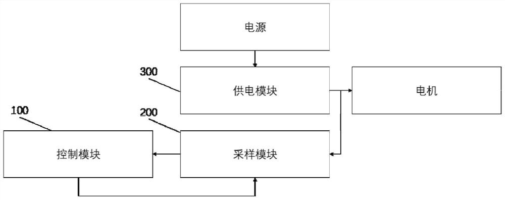
[0003] The main purpose of the present invention is to propose a permanent magnet synchronous motor drive circuit, method, electronic equipment and medium, aiming to solve the problem that the fixed sampling range in the prior art makes it impossible to obtain accurate sampling feedback data

Method used


Image

  • Permanent magnet synchronous motor driving circuit and method, electronic equipment and medium
  • Permanent magnet synchronous motor driving circuit and method, electronic equipment and medium
  • Permanent magnet synchronous motor driving circuit and method, electronic equipment and medium

Examples


Embodiment Construction

[0036] It should be understood that the specific embodiments described herein are only used to explain the present invention, but not to limit the present invention.

[0037] The technical solutions in the embodiments of the present invention will be clearly and completely described below with reference to the accompanying drawings in the embodiments of the present invention. Obviously, the described embodiments are only a part of the embodiments of the present invention, but not all of the embodiments. Based on the embodiments of the present invention, all other embodiments obtained by those of ordinary skill in the art without creative efforts shall fall within the protection scope of the present invention.

[0038] It should be noted that all directional indications (such as up, down, left, right, front, back...) in the embodiments of the present invention are only used to explain the The relative positional relationship between the components, the movement situation, etc.,...


PUM


Abstract

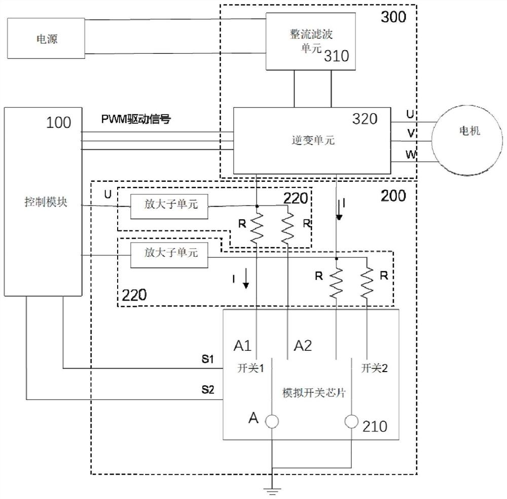
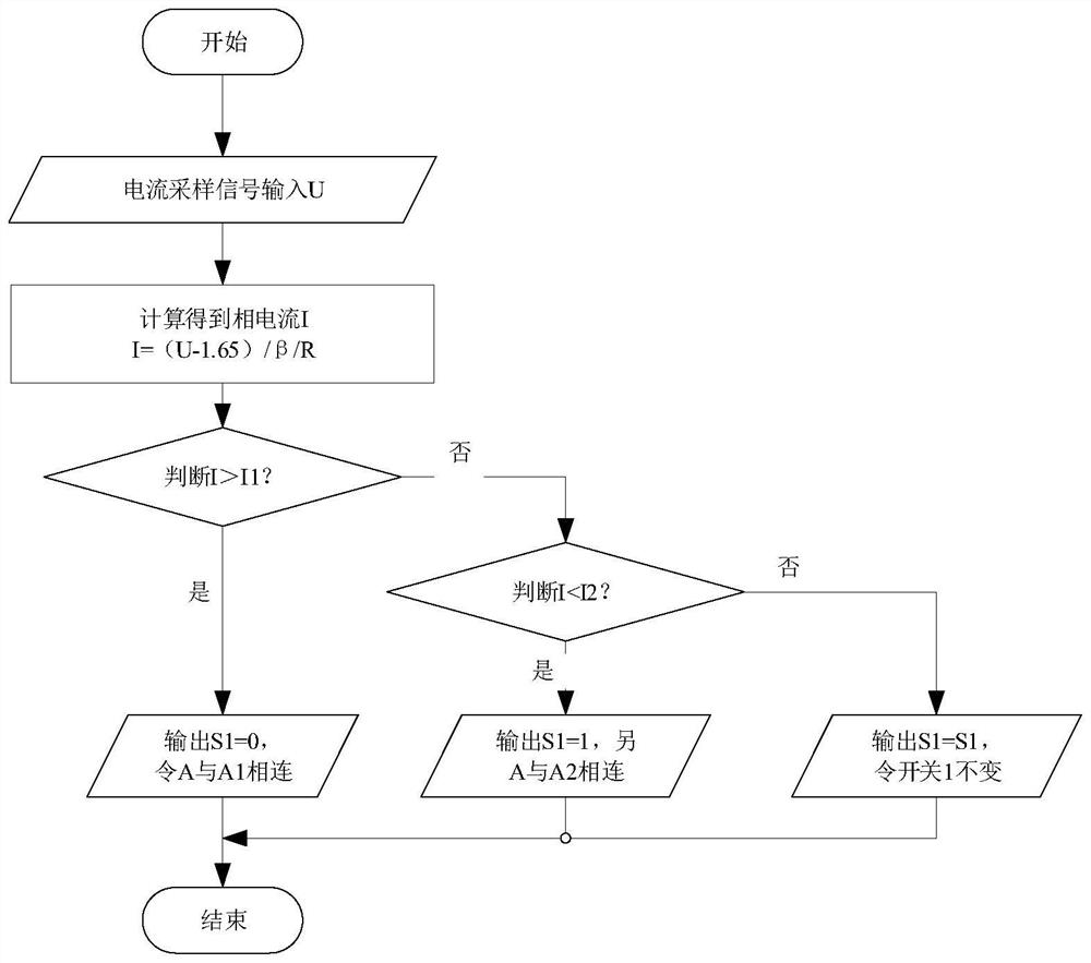
The invention provides a permanent magnet synchronous motor driving circuit and method, electronic equipment and a medium. The permanent magnet synchronous motor driving circuit is connected with a power supply and a motor. The circuit comprises a sampling module which is used for sampling an output electric signal of a power supply module to obtain a sampling signal and sending the sampling signal to a control module; the control module is used for receiving the sampling signal sent by the sampling module, determining an adjustment parameter of the sampling module according to the sampling signal, and sending a control signal corresponding to the adjustment parameter to the sampling module; and the sampling module is also used for adjusting the sampling parameter into the adjustment parameter when the control signal is received. According to the invention, the control module confirms the motor operation state based on the collected sampling signal, and adjusts the sampling parameter based on the motor operation state, so that the sampling parameter can be matched with the motor operation state, the sampling range is improved, and more accurate sampling data is obtained.

Description

technical field [0001] The invention relates to the field of circuit control, in particular to a drive circuit, method, electronic device and medium of a permanent magnet synchronous motor. Background technique [0002] Existing permanent magnet synchronous motors are widely used in all walks of life. Different application environments have slightly different control methods. In order to obtain an accurate closed-loop control system, a current sampling circuit will be added at the output end, and based on sampling However, due to the limitations of the existing control circuit, the voltage range and current range of full-frequency sampling are fixed. With the development of the industry, the operating range of the motor is getting higher and higher. If a fixed sampling range is used, the operating range of the motor cannot be widened, and accurate sampling feedback data cannot be obtained, so that the load cannot run stably, so that the speed control accuracy deviation is to...

Claims


Application Information

Patent Timeline
IPC IPC(8): H02P6/00H02P25/024H02P27/08
CPCH02P6/00H02P25/024H02P27/08Y02P80/10
Inventor 甘典志官猛魏会军徐常升程海珍
Owner GREE ELECTRIC APPLIANCES INC
Learn More