
monitoring buoy

A technology for buoys and buoys, applied in buoys, special-purpose ships, reducing greenhouse gases, etc., can solve the problems of buoy overturning, impact damage, etc., and achieve the effect of reducing electrical device damage, avoiding impact damage, and high efficiency

Active Publication Date: 2021-07-13
浙江省海洋技术服务中心
View PDF11 Cites 0 Cited by
  • Summary
  • Abstract
  • Description
  • Claims
  • Application Information

AI Technical Summary

Problems solved by technology

[0004] The purpose of the present invention is to provide a monitoring buoy, which adopts natural environmental protection, unpowered and simple water cooling and heat dissipation settings to solve the problem of circulating heat dissipation of electrical components of the buoy, reduce damage to electrical components and ensure operational stability, and at the same time solve the problem that the buoy is prone to overturning under the influence of wind and waves in the sea It is also beneficial to avoid impact damage to the floating body and its internal components, and realize multi-functional integration; it is more environmentally friendly and sustainable to replace the remote power supply with the wind energy conversion device, and it can realize the telescopic movement and angle adjustment movement of the blades to improve the utilization rate of wind energy. When the wind speed exceeds the limited wind speed, it can not only form electric overload protection but also protect weak blades from damage

Method used


Image

  • monitoring buoy
  • monitoring buoy
  • monitoring buoy

Examples


Embodiment 1

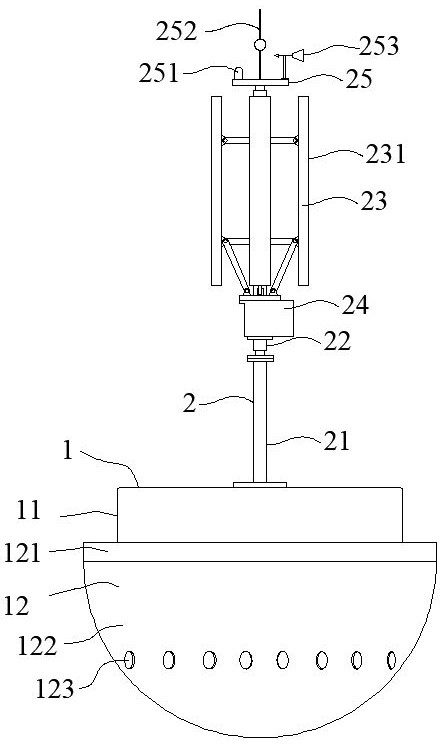
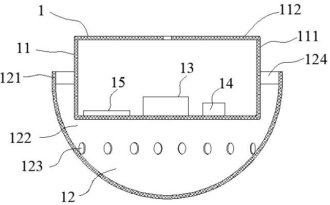
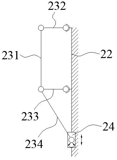
[0024] Such as Figure 1-5 As shown, the monitoring buoy includes a buoyancy device 1, and the buoyancy device 1 is composed of a buoyancy body 11 and a transducing device 12 surrounding the lower half of the outside of the buoyancy body 11; a power generation device 13, an accumulator 14 and a plurality of calculation devices are also installed in the buoyancy body 11 15. The power generation device 13 is connected to the electric storage device 14 and the computing device 15 through a cable; a wind energy conversion device 2 connected to the power generation device 13 through a cable is installed above the floating body 11; And the blade device 23 and telescoping device 24 of angle adjustment motion. The buoyancy device 1 includes a floating body 11 and a transducing device 12 surrounding the outer lower half of the floating body 11. The spherical transducing device 12 is used to surround the floating body 11 and form a certain distance. The electrical components inside are...

Embodiment 2

[0035]When the monitoring buoy of the present invention is actually used, the monitoring buoy is placed in the target sea area, and can be anchored or floated on the sea according to needs. After the buoy is placed, the seawater is first immersed in the transducer device 12 and is always maintained under the buoyancy of the buoy 11. The buoy floats vertically on the sea surface, and utilizes the tidal current pouring in from the upper surface of the ring body 121 to increase the water flow exchange rate in the inner space of the space to realize the circulation and heat dissipation of the electrical components in the buoyant body 11 to ensure its operation stability, and the energy conversion device 12 By increasing the amount of immersion water and lowering the center of gravity, the center of gravity of the buoy is maintained stable, anti-overturning and forms a protective cover to prevent impact; at the same time, after the wind energy conversion device 2 is put in stably, th...


PUM


Abstract

The invention discloses a monitoring buoy, which belongs to the technical field of marine monitoring. The buoyancy device includes a buoyancy body and an energy conversion device. The buoyancy body is equipped with a power generation device, an electric storage device and a number of computing devices. The upper part is connected with the power generation device and can realize the telescopic movement of the blade. And angle adjustment movement of the wind energy conversion device. Solve the problem of circulating heat dissipation through the simple water-cooling heat dissipation setting without power and environmental protection, and ensure the operation stability of electrical components, anti-overturning, and anti-collision; wind power supply is more environmentally friendly and sustainable, and the blade angle can be adjusted to improve wind energy utilization. When the wind speed is too high It forms power overload protection and protects weak blades; the computing device performs data collection and processing and interacts with the remote terminal to realize real-time monitoring and control. The sampling data is more accurate, the sampling process is easier, and the efficiency is higher. It can perform buoy positioning and water monitoring. Real-time monitoring, long service life, low maintenance cost, easy transportation and delivery, and good popularity.

Description

technical field [0001] The invention belongs to the technical field of ocean monitoring, in particular to a monitoring buoy. Background technique [0002] The water monitoring buoy is an unmanned platform for ocean exploration, and a multi-information transmission channel from the water surface to satellites, shore-based and nearby ships. It can be used repeatedly and flexibly, and has a wide range of applications. However, as more and more functional requirements lead to insufficient power supply or the difficulty and cost of remote power supply, which may cause damage to the environment, people are gradually developing towards the development of natural and environmentally friendly natural energy. [0003] Wind power generation converts the kinetic energy of the wind into mechanical kinetic energy, and then converts the mechanical energy into electrical kinetic energy. It does not require fuel, nor does it produce radiation or air pollution. It is low-cost and renewable, a...

Claims


Application Information

Patent Timeline
Patent Type & Authority Patents(China)
IPC IPC(8): B63B22/00F03D9/11F03D9/32
CPCB63B22/00B63B2022/006F03D9/11F03D9/32Y02E10/72Y02E10/728Y02E70/30
Inventor 茅克勤冯振洲陆彩红许超翔
Owner 浙江省海洋技术服务中心
Learn More