
Harmonic source identification method

An identification method and harmonic source technology, applied in the field of harmonic source identification, can solve problems such as division and inability to cause harmonic pollution, and achieve high accuracy, good engineering use value, and good practicability

Inactive Publication Date: 2015-03-11
YUNNAN POWER GRID CO LTD ELECTRIC POWER RES INST
View PDF5 Cites 23 Cited by
  • Summary
  • Abstract
  • Description
  • Claims
  • Application Information

AI Technical Summary

Problems solved by technology

[0008] The invention proposes a harmonic source identification method, which solves the problem that the harmonic pollution responsibility cannot be accurately divided in the prior art

Method used


Image

  • Harmonic source identification method
  • Harmonic source identification method
  • Harmonic source identification method

Examples


Embodiment 1

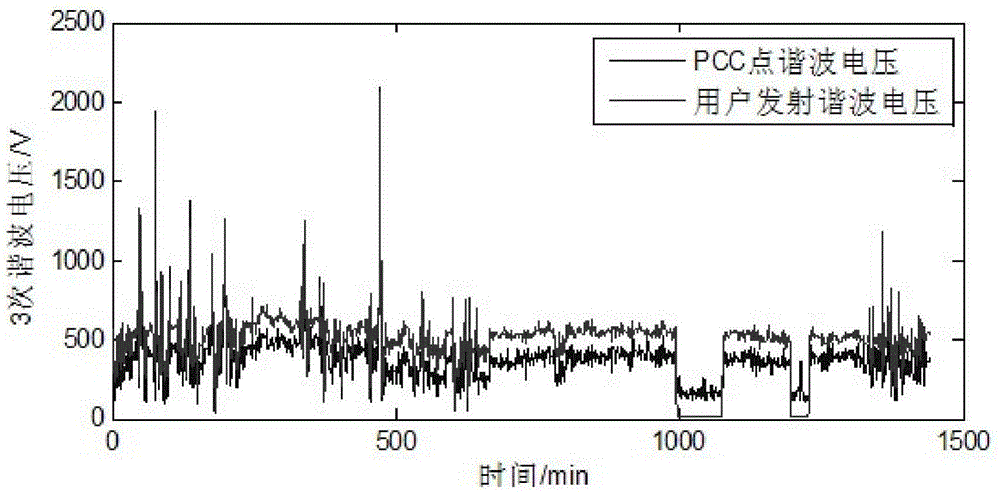
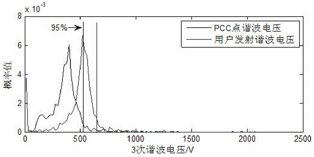
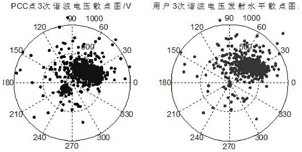
[0049] For a 220kV busbar of a nonlinear user, the sampling frequency of the test data is 9000Hz. After performing fast Fourier transform on the sampled three-phase voltage and current data every minute, the amplitude and phase angle of each harmonic can be obtained, that is, the harmonic Input value for wave emission level calculation. Using the algorithm principle of the present invention to calculate, the harmonic emission level can be obtained. figure 1 , figure 2 and image 3 The user emission level trend diagram, probability distribution diagram and scatter comparison diagram of the third harmonic are given respectively. Judging from the comparison chart results of the simulation test, the estimation results of the present invention have high reliability, accuracy, and validity.

Embodiment 2

[0051] Such as Figure 4 As shown, in the test, the three-phase FLUCK 6100A is used as the standard signal source, the output signal is applied to the test circuit board, and the voltage and current waveform at the PCC point is collected by the Yokogawa DL 750 waveform recorder, and finally the computer is used to read the DL 750 to obtain The signal of the present invention can be verified by performing secondary processing on the signal.

[0052] According to the current source characteristics of the harmonic source and the impedance characteristics of the linear load at the harmonic frequency point, Professor Thunberg E proposed to use the Norton equivalent circuit to carry out the harmonic source on both sides of the common connection point PCC (system side and user side) modeling. Since the proposed Norton model has been proved to be feasible, all current methods for quantitative location analysis of harmonic sources on both sides of the common connection point are to an...


PUM


Abstract

The invention provides a harmonic source identification method which comprises the following steps: performing responsibility allocation on harmonic pollution through the harmonic voltage emission level of a user, wherein the harmonic voltage emission level of the user at a time is represented through the variable quantity of harmonic voltage or current at a time at a point of common coupling before and after the user accesses to a power system; positioning an accurate point of a harmonic source through harmonic emission level evaluation to the maximum extent. The method has the benefits that an algorithm provided by the invention can quickly determine the harmonic source, is high in accuracy and practicality, and has very good project utilization values.

Description

technical field [0001] The invention relates to the technical field of harmonic source positioning at a common connection point of a power grid, in particular to a harmonic source identification method. Background technique [0002] At present, the use of electric energy is increasingly dependent on the power supply with controllable frequency and voltage. However, power generation and transmission are still running at nominally constant levels, so some form of power conditioning or transformation is required to compensate, usually This is accomplished using power electronics, which can distort voltage and current waveforms. [0003] With the development of industry, more and more non-linear industrial users are connected to the power grid, causing a large amount of harmonic current to be injected into the power system. When the harmonic current flows through the harmonic impedance, harmonic voltage will be generated at the common connection point of the power grid. , which...

Claims


Application Information

Patent Timeline
Patent Type & Authority Applications(China)
IPC IPC(8): G01R23/16
Inventor 沈鑫闫永梅曹敏马红升
Owner YUNNAN POWER GRID CO LTD ELECTRIC POWER RES INST
Learn More