Mirror with variable reflectivity
A mirror and variable technology, applied in mirrors, instruments, optics, etc., can solve problems such as inconvenience, increased difficulty of operation, and complicated devices
Inactive Publication Date: 2015-03-11
SHENZHEN UNIV
View PDF5 Cites 3 Cited by
- Summary
- Abstract
- Description
- Claims
- Application Information
AI Technical Summary
Problems solved by technology
When it is necessary to change the reflectivity in practical applications, the general method is to replace the reflector, or add an attenuation device in front of the reflector to adjust the reflectivity, which not only complicates the device, increases the difficulty of operation, but is also very inconvenient
Method used
View moreImage
Smart ImageViewing Examples

Examples
Embodiment Construction
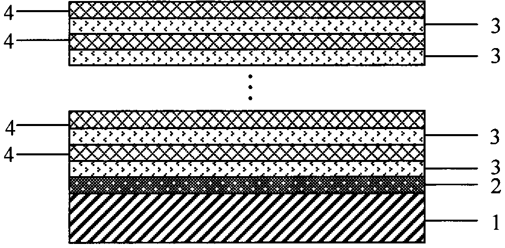
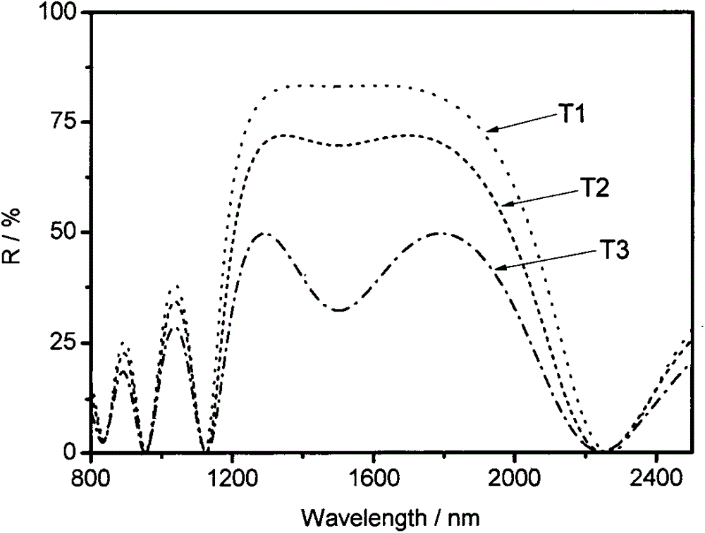
[0016] Deposit a conductive film layer 2 on the polished K9 glass substrate 1 as a heating layer, and then deposit a layer of optical thickness λ on the surface of the heating layer 2 0 VO of / 4 2 thin film 3, as a phase change layer, and then deposit a layer of optical thickness λ on the phase change layer 3 0 4 SiO 2 Thin film 4, as a low refractive index layer, so repeated, VO 2 Phase change layer 3 and SiO 2 The low refractive index layer 4 is plated for 4 periods in total, where λ 0 1550nm. Pass currents of different sizes to the conductive layer 2, and measure the spectral reflectance curves at three different temperatures T1, T2, and T3. figure 2 .
Login to View More PUM
 Abstract
The invention provides a mirror with variable reflectivity. The mirror with variable reflectivity is a multilayer membrane structure optical element which is prepared on a substrate by adopting a physical vapor deposition membrane coating technology under certain conditions based on the light interference principle with a conductive membrane, VO2 and SiO2 acting as main membrane layer material. Adjustment of infrared light reflectivity can be realized via temperature adjustment within range of room temperature to 80 DEG C. The reflecting mirror is high in anti-interference performance and great in stability.
Description
technical field [0001] The invention relates to an optical reflector, in particular to an infrared multilayer optical reflector based on the principle of light interference. technical background [0002] The invention relates to an optical reflector, especially an infrared optical reflector. [0003] Reflector is a device that reflects light. Infrared reflector is an important optical component that reflects infrared light. It is widely used in lasers, remote sensing, communications, analytical instruments, laser processing and other fields. In general, the reflectivity of infrared reflectors for specific wavelengths is usually constant. When it is necessary to change the reflectivity in practical applications, the general method is to replace the reflector, or add an attenuation device in front of the reflector to adjust the reflectivity, which not only complicates the device, increases the difficulty of operation, but is also very inconvenient. The invention designs a re...
Claims
Login to View More Application Information
Patent Timeline
 Patent Type & Authority Applications(China)
IPC IPC(8): G02B5/08G02F1/01
CPCG02B5/0833G02F1/009
Inventor 张东平朱茂东李岩刘毅范平梁广兴郑壮豪罗景庭
Owner SHENZHEN UNIV