

Liquid ejecting apparatus, print head unit, and drive substrate
A liquid and substrate technology, applied in printing devices, printing, etc., can solve the problems of switching element switching loss and heat generation, additional heat dissipation components, and difficulty in increasing size, and achieve the effect of simple structure and stable operation
- Summary
- Abstract
- Description
- Claims
- Application Information
AI Technical Summary
Problems solved by technology
Method used
Image

Examples
Embodiment approach 1
[0061] (Outline of liquid ejection device)
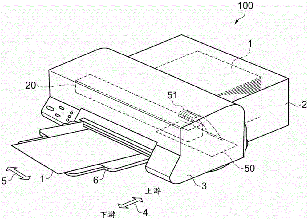
[0062] figure 1 It is a perspective view showing the outline of the liquid ejection device according to Embodiment 1. First, an overview of the printer 100 as the liquid ejection device according to the present embodiment will be described.
[0063] The printer 100 is an inkjet printer that prints on paper 1 as a print medium delivered from the rear paper feed tray 2 by the print head unit 20 and then unloads the paper 1 to the front paper output tray 6 side. In the following description, the direction in which the paper 1 is conveyed is referred to as the conveyance direction 4 , and the direction intersecting the conveyance direction (the width direction of the paper 1 ) is described as the paper width direction 5 . In addition, in the transport direction 4 , the paper feed tray 2 side is referred to as the upstream side, and the delivery (front) side is referred to as the downstream side.
[0064] The print head unit 20 is equ...
Deformed example 1
[0240] use Figure 13 to explain.
[0241] In Embodiment 1, a case was described in which a glass epoxy substrate is used for the main substrate 50 , but it is not limited to this configuration, and any substrate may be used as long as a through hole can be formed. For example, ceramic substrates, Teflon (registered trademark) substrates, glass / composite material substrates, paper epoxy resin substrates, flexible substrates, and the like can also be used.
[0242] In addition, it is not limited to double-sided substrates, but can also be applied to multilayer substrates. In this case, it is not necessary for the through hole to penetrate from the front surface to the back surface. For example, the through hole on the front surface may be connected to the back surface through another through hole through the (solid) pattern of the intermediate layer. In other words, it is only necessary to form a path capable of transferring heat from the front surface to the rear surface.
...
Deformed example 2
[0246] use Figure 16 to explain.
[0247] In Embodiment 1 and Modification 1, the structure in which the drive circuit 44 is mounted on the main substrate 50 has been described, but it is not limited to this structure. If a double-sided through-hole substrate is used, a separate structure (substrate) is also possible. . For example, it can also be assembled with figure 1The structure of the print head unit 20 independent drive substrate (on which the drive circuit 44 is mounted). In the case of this structure, the drive board is attached to the metal member of the print head unit 20 . Alternatively, a structure in which the circuit of the head substrate 15 is also mounted on the drive substrate and integrated into the print head unit 20 may be used.
[0248] Even with these configurations, since the above-described effect of heat dissipation can be obtained, the same effects as those of the above-described embodiment and modifications can be obtained.
PUM
| Property | Measurement | Unit |
|---|---|---|
| Thermal conductivity | aaaaa | aaaaa |
Abstract
Description
Claims
Application Information