Clamping device and plasma processing device

A clamping device and processing technology, which is applied in semiconductor/solid-state device manufacturing, discharge tubes, electrical components, etc., can solve the problems of reducing the service life of the cover plate 2, long disassembly and assembly time of the clamping device, and cumbersome disassembly and assembly procedures. , to simplify the disassembly steps, save the disassembly time, and improve the service life.

Active Publication Date: 2015-03-18
BEIJING NAURA MICROELECTRONICS EQUIP CO LTD
View PDF2 Cites 10 Cited by
  • Summary
  • Abstract
  • Description
  • Claims
  • Application Information

AI Technical Summary

Problems solved by technology

However, due to the large number of fastening screws 4, this not only leads to a longer disassembly and assembly time of the clamping device, but also cumbersome disassembly and assembly procedures, thereby reducing process efficiency; Therefore too many fastening screws 4 will increase the probability of cracks appearing in the through hole 21 of the cover plate 2, thereby reducing the service life of the cover plate 2

Method used


Image

  • Clamping device and plasma processing device
  • Clamping device and plasma processing device
  • Clamping device and plasma processing device

Examples


Embodiment Construction

[0025] In order for those skilled in the art to better understand the technical solutions of the present invention, the clamping device and the plasma processing equipment provided by the present invention will be described in detail below with reference to the accompanying drawings.

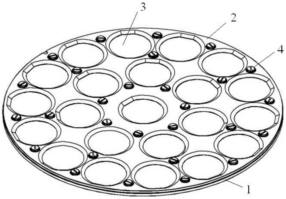
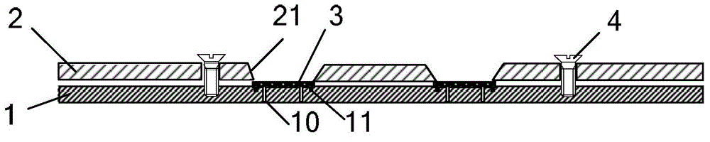
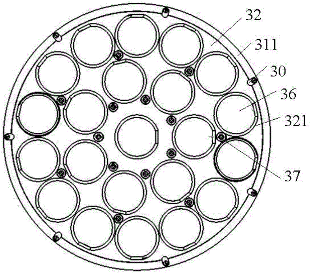
[0026] Figure 3A A top view of the clamping device provided by the embodiment of the present invention. Figure 3B for Figure 3A partial sectional view. Please also refer to Figure 3A and Figure 3B , the clamping device includes a tray 31, a cover plate 32 and a fastening unit. Wherein, the cover plate 32 cooperates with the tray 31 to clamp the workpiece 36 to be processed between the two. In this embodiment, the tray 31 is provided with a plurality of bearing positions for placing the workpiece 36 to be processed. The bearing positions are arranged on the circumference of different radii of the pallet 31, for example Figure 3A The middle bearing position is arranged on the tray 31 i...


PUM


Abstract

The invention provides a clamping device and a plasma processing device. The clamping device comprises a tray, a cover plate and a fastening unit, wherein the fastening unit comprises a support part and a plurality of fastening components; the support part is of an annular structure, surrounds the outside of the cover plate and is connected with the tray; the plurality of fastening components are arranged on the support part and are arranged at intervals along the periphery of the cover plate; each fastening component comprises a pressing block, a fastening part and an elastic part; the pressing blocks are rotatably connected with the support part by virtue of the fastening parts; each pressing block is provided with a cantilever; the cantilevers are mutually superposed with the edge area of the cover plate when the cantilevers are driven to rotate to a first position by the pressing block; the cantilevers are mutually separated from the edge area of the cover plate when the cantilevers are driven to rotate to a second position by the pressing blocks; the fastening parts are used for applying elastic force to the upper surface of the tray by virtue of an elastic part, so that the cantilevers are used for pressing the edge area of the cover plate when in the first position. By virtue of the clamping device, the demounting time can be saved, the demounting steps can be simplified, and the cracking probability of the cover plate can also be reduced.

Description

technical field [0001] The invention belongs to the field of semiconductor equipment manufacturing, and in particular relates to a clamping device and plasma processing equipment. Background technique [0002] With the continuous development of microelectronics technology, the competition of related production enterprises is becoming more and more fierce. Reducing costs and improving production efficiency are common means to improve the competitiveness of enterprises. For example, in order to improve production efficiency and reduce production costs, LED light source manufacturers use clamping devices to simultaneously move and etch multiple sapphire substrates during the patterned sapphire substrate (Patterned Sapphire Substrates, hereinafter referred to as PSS) etching process. To meet the increasing market demand. It is well known that the structure of the holding device has a great influence on the etching effect and availability of the wafer. [0003] figure 1 It is ...

Claims


Application Information

Patent Timeline
Patent Type & Authority Applications(China)
IPC IPC(8): H01L21/687H01J37/20
CPCH01J37/20H01L21/68785
Inventor 侯宁
Owner BEIJING NAURA MICROELECTRONICS EQUIP CO LTD
Why Eureka
Try Eureka