Binding system of spraying and binding machine

A binding machine and drive motor technology, applied in the field of binding systems, to achieve the effects of saving human resources, simple structure, and easy operation

Active Publication Date: 2015-03-25
平湖市盛泰五金制品有限公司
View PDF7 Cites 14 Cited by
  • Summary
  • Abstract
  • Description
  • Claims
  • Application Information

AI Technical Summary

Problems solved by technology

[0004] In order to solve the above-mentioned problems in the prior art, the present invention aims to provide a binding system of a spraying binding machine which has the advantages of simple structure, low cost, easy operation, low labor intensity, hi

Method used


Image

  • Binding system of spraying and binding machine
  • Binding system of spraying and binding machine
  • Binding system of spraying and binding machine

Examples


Embodiment Construction

[0018] In order to make the technical means, creative features, goals and effects achieved by the present invention easy to understand, the present invention will be further described below in conjunction with specific illustrations.

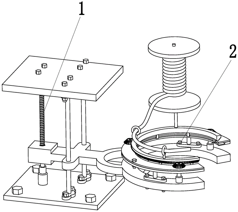
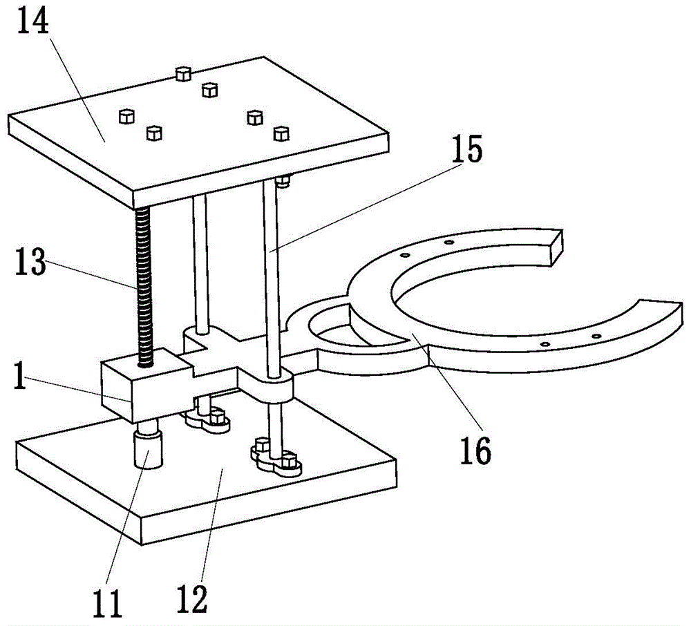
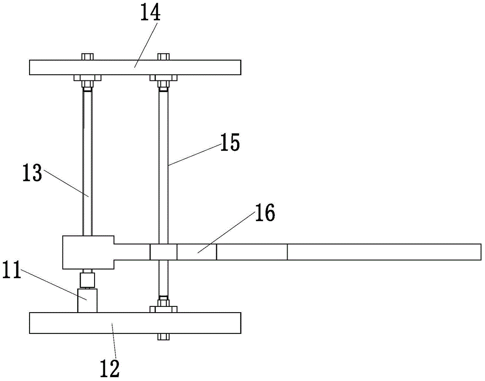
[0019] Such as Figure 1 to Figure 8 As shown, a binding system of a spray binding machine includes a lifting device 1 and a rotating device 2, and the rotating device 2 is installed on the right side of the lifting device 1; the lifting device 1 includes a drive motor 11, a lower base plate 12 , leading screw 13, upper base plate 14, two optical shafts 15 and lifting platform 16, described driving motor 11 is installed on the lower base plate 12 through motor base, and the output shaft of driving motor 11 and the lower end of leading screw 13 pass through The shaft coupling is connected, and the drive motor 11 provides lifting power for the present invention. The upper end of the screw 13 is connected with the upper bottom plate 14 through a be...


PUM


Abstract

The invention relates to a binding system of a spraying and binding machine. The binding system comprises a lifting device and a rotating device. The rotating device is installed on the right side of the lifting device. The lifting device comprises a drive motor, a lower bottom board, a lead screw, an upper bottom board, two polish shafts and a lifting platform. The drive motor is installed on the lower bottom board through a motor seat. An output shaft of the drive motor is connected with the lower end of the lead screw through a coupler. The upper end of the lead screw is connected with the upper bottom board through a bearing with a seat. The lower ends of the polish shafts are installed on the lower bottom board through bearings with seats. The upper ends of the polish shafts are installed on the upper bottom board through bearings with seats. The lifting platform is connected with the lead screw through threads and connected with the two polish shafts in a clearance fit mode. The binding system has the advantages that the structure is simple, manufacturing cost is low, operation is easy and convenient, labor intensity is low, work efficiency is high, straw ropes are twisted evenly, and the straw ropes can be rapidly and evenly twisted.

Description

technical field [0001] The invention relates to the technical field of garden and forestry machinery, in particular to a binding system of a spraying binding machine. Background technique [0002] In the cold winter, on both sides of the street, you can see that sanitation workers will take measures such as wrapping straw ropes on the trunks of greening trees. The purpose of wrapping straw ropes on the trunks is: 1. It can keep warm for the winter of the tree species that are not resistant to freezing Work; 2. It has the function of moisturizing the trunk, and can keep the grass rope moist through rainfall or artificial watering, thereby improving the survival rate of trees; 3. The grass rope also has the function of blocking sunlight and preventing bark burns. [0003] However, the above-mentioned measures such as wrapping the trunks with straw ropes are all done manually by sanitation workers. Due to the continuous acceleration of the pace of modern cities, the city has hi...

Claims


Application Information

Patent Timeline
IPC IPC(8): A01G13/02
CPCA01G13/0237
Inventor 刘俊
Owner 平湖市盛泰五金制品有限公司
Why Eureka
Try Eureka