Novel laboratory fume cupboard

A laboratory fume hood technology, which is applied in the direction of cleaning methods and utensils, dust removal, chemical instruments and methods, etc., can solve the problems that cannot guarantee the complete discharge of harmful gases, air pollution, harmful to health, etc., so as to facilitate popularization and use, The effect of strong structure and simple structure

Inactive Publication Date: 2015-03-25
TIANCHANG MING HUI LAB EQUIP
View PDF6 Cites 6 Cited by
  • Summary
  • Abstract
  • Description
  • Claims
  • Application Information

AI Technical Summary

Problems solved by technology

[0002] Experimental equipment is widely used in a series of research places such as hospitals, schools, and various research institutes, including various laboratory countertops, laboratory instruments, ventilation system air supply and cleaning systems, etc., but currently the most used in laboratories The most important is a series of equipment such as test benches, fume hoods, etc. In the laboratory, due to the use of various chemical substances, the air pollution in the laboratory is often caused. Some substances not only smell bad, but also harmful to health. In order to create a healthy and safe Therefore, it can be achieved by using a fume hood. The main body of an ordinary fume hood is a box, and an exhaust channel is set on the box, so that harmful gases will be discharged during the experiment. However, ordinary fume hoods on the market are actually There are still many defects in the use of the machine, and it cannot guarantee that all harmful gases will be discharged, and there are still great potential safety hazards

Method used


Image

  • Novel laboratory fume cupboard
  • Novel laboratory fume cupboard
  • Novel laboratory fume cupboard

Examples


Embodiment Construction

[0015] In order to make the technical means, creative features, goals and effects achieved by the present invention easy to understand, the present invention will be further described below in conjunction with specific illustrations.

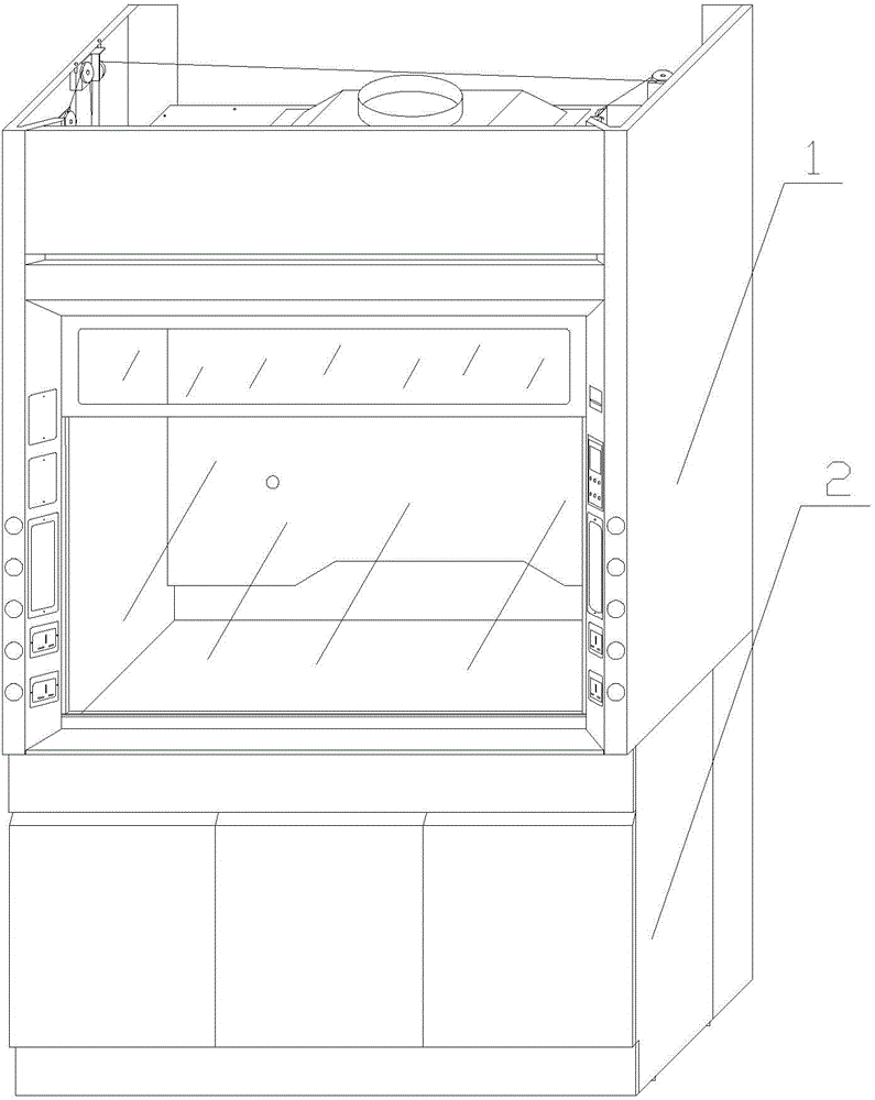
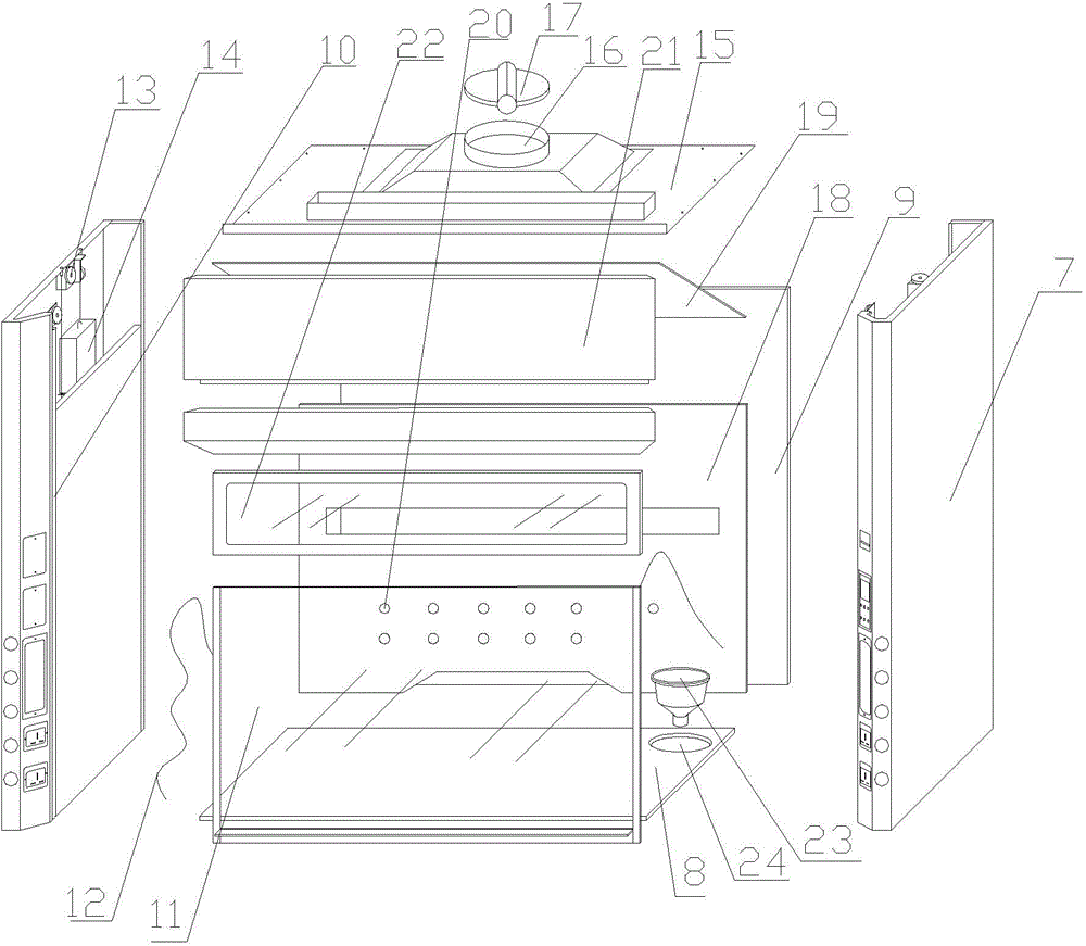
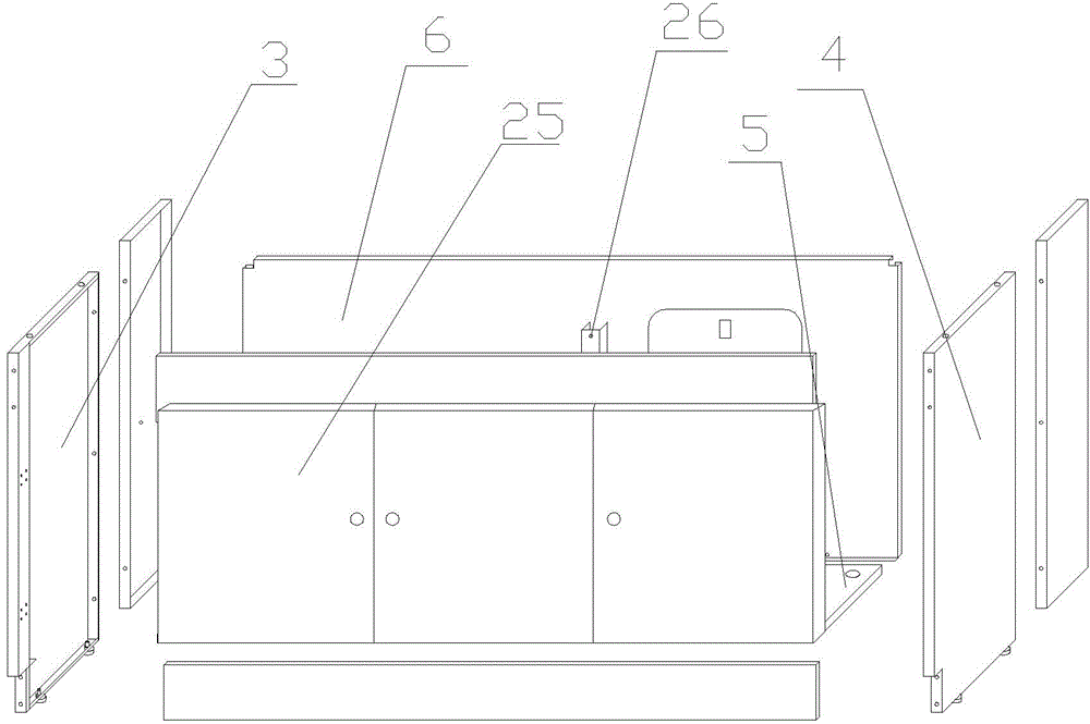
[0016] Such as figure 1 , figure 2 and image 3 As shown, a new type of laboratory fume hood, the main body is composed of an upper cabinet body 1 and a lower cabinet body 2, characterized in that: the lower cabinet body 1 is a left baffle 3, a right baffle 4, and a bottom plate 5 and the support frame formed by the back cover plate 6, the upper cabinet body 1 includes two sets of side plates 7 arranged perpendicularly to each other, a table 8 is arranged at the bottom between the side plates 7, and a rear plate 9 is connected to the rear end of the side plates 7, and the side plates 7 The front end of the plate 7 is provided with a card slot 10, and a glass door panel 11 that can be pushed and pulled up and down is arranged in the card slot ...


PUM


Abstract

The invention relates to the field of experiment equipment manufacturing, in particular to a novel laboratory fume cupboard. A body is composed of an upper cupboard body and a lower cupboard body. The lower cupboard body is a supporting frame which is formed by a left baffle, a right baffle, a bottom plate and a back sealing plate. The upper cupboard body comprises two sets of perpendicular side plates. A table board is arranged at the bottom of the space among the side plates. A rear plate is connected to the rear ends of the side plates. Clamping grooves are formed in the front ends of the side plates, a glass door sheet capable of being pushed and pulled vertically is arranged in the clamping grooves, the two sides of the glass door sheet are each provided with one pull rope, the side plates are hollow, the top of the inner side of each side plate is provided with a pulley, and each pull rope is wound around the corresponding pulley to be connected with a weight. A top plate is fixed to the tops of the side plates, an air outlet is formed in the top plate, and a check valve is arranged on the air outlet. A vertical flow guide plate perpendicular to the table board is arranged at the front end of the rear plate, an inclined flow guide plate is arranged at the top of the vertical flow guide plate, and exhaust holes are formed in the vertical air deflector. The novel laboratory fume cupboard is novel in design and guarantees that harmful gas in a laboratory is thoroughly exhausted.

Description

technical field [0001] The invention relates to the field of experimental equipment manufacturing, in particular to a novel laboratory fume hood. Background technique [0002] Experimental equipment is widely used in a series of research places such as hospitals, schools, and various research institutes, including various laboratory countertops, laboratory instruments, ventilation system air supply and cleaning systems, etc., but currently the most used in laboratories The most important is a series of equipment such as test benches, fume hoods, etc. In the laboratory, due to the use of various chemical substances, the air pollution in the laboratory is often caused. Some substances not only smell bad, but also harmful to health. In order to create a healthy and safe Therefore, it can be achieved by using a fume hood. The main body of an ordinary fume hood is a box, and an exhaust channel is set on the box, so that harmful gases will be discharged during the experiment. Howe...

Claims


Application Information

Patent Timeline
Patent Type & Authority Applications(China)
IPC IPC(8): B08B15/04
CPCB08B15/023
Inventor 陆发辉
Owner TIANCHANG MING HUI LAB EQUIP
Why Eureka
Try Eureka