Improved electric spindle

A technology of electric spindle and shaft core, which is applied in the direction of large fixed members, clamping, support, etc., can solve the problem of high cost, and achieve the effect of easy assembly and cost saving

Active Publication Date: 2015-03-25
GUANGZHOU HAOZHI ELECTROMECHANICAL
View PDF14 Cites 31 Cited by
  • Summary
  • Abstract
  • Description
  • Claims
  • Application Information

AI Technical Summary

Problems solved by technology

However, in order to meet the processing requirements, it is often necessary to replace different tools on the shaft core assembly. Therefore, each tool must be equipped with an ultrasonic transducer, resulting in a higher cost for applying the ultrasonic function.

Method used


Image

  • Improved electric spindle
  • Improved electric spindle
  • Improved electric spindle

Examples


Embodiment Construction

[0021] In the following, the present invention will be further described with reference to the accompanying drawings and specific implementations, so as to more clearly understand the technical ideas claimed by the present invention.

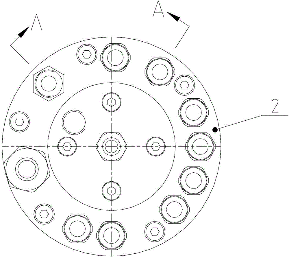
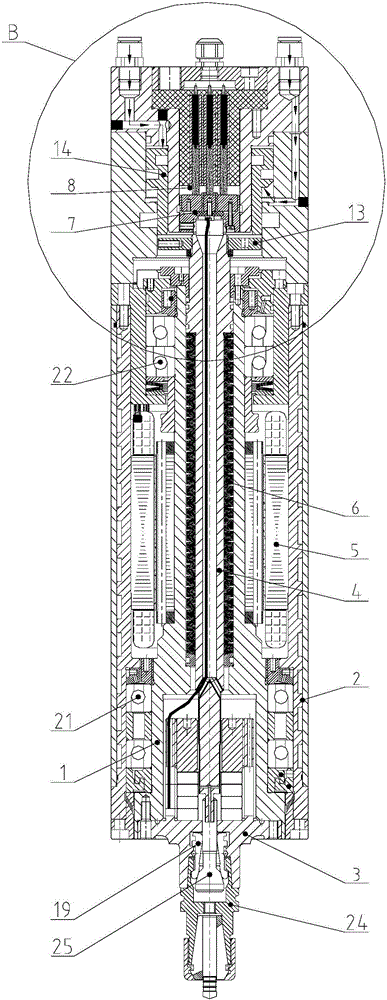
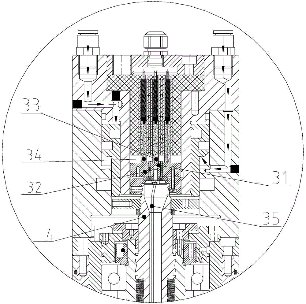
[0022] Such as figure 1 , 2 , 3 and 4 show an improved electric spindle of the present invention, which includes a body 2, a stator 5 fixed in the body 2, and a shaft assembly installed in the body 2; The matched rotor; the shaft core assembly includes a hollow shaft core 1, a tie rod 4 located in the shaft core 1; the lower end of the shaft core 1 is fixed with an ultrasonic transducer 3, the ultrasonic transducer 3 A mounting cavity is formed, and a pull claw 19 is provided in the mounting cavity; the improved electric spindle also includes a horn 24 equipped with a cutter, and the upper end of the horn 24 is mounted on the ultrasonic transducer 3 and the pull claw 19 The lower end of the pull rod 4 extends into the installation cavity, the pull ...


PUM


Abstract

The invention discloses an improved electric spindle which comprises a machine body, a stator and a central spindle assembly mounted in the machine body. The central spindle assembly is provided with a rotor matched with the stator. The central spindle assembly comprises a hollow central spindle and a pull rod located in the central spindle. An ultrasonic transducer is fixedly arranged at the lower end of the central spindle, a mounting cavity is formed in the ultrasonic transducer, and a pull claw is arranged in the mounting cavity. The electric spindle further comprises an amplitude-change pole which is provided with a cutter, and the upper end of the amplitude-change pole is mounted between the ultrasonic transducer and the pull claw. The pull claw is movably arranged at the lower end of the pull rod in a sleeving mode, and a strutting part is arranged on the pull rod. A driving part which is used for driving the pull rod to move downwards and driving the strutting part to be away from the pull claw to enable the pull claw to be automatically contracted is mounted in the machine body. An elastic element is mounted between the pull rod and the central spindle. The improved electric spindle can improve the processing effect, and further can prolong the service life of the cutter. Moreover, the abrasion of a center carbon brush and an outer carbon brush can further be reduced, and assembling is easy.

Description

Technical field [0001] The invention relates to an improved electric spindle. Background technique [0002] The electric spindle generally includes a body, a stator fixed in the body, and a shaft core component installed in the body; the shaft core component has a rotor matched with the stator; and the tool is installed on the lower end of the shaft core component. During the working process of the electric spindle, the shaft core assembly rotates to drive the tool to rotate to cut the workpiece. However, the processing effect of the existing electric spindle is poor and cannot meet people's requirements. In order to solve the above problems, a new ultrasonic electric spindle has appeared on the market. In order to realize the ultrasonic vibration function, an ultrasonic transducer is often installed on the tool to convert electrical energy into mechanical vibration energy through the ultrasonic transducer, thereby realizing ultrasonic vibration. However, in order to meet the ...

Claims


Application Information

Patent Timeline
Patent Type & Authority Applications(China)
IPC IPC(8): B23B19/02
CPCB23Q1/70B23Q3/157
Inventor 汤秀清陈帝游
Owner GUANGZHOU HAOZHI ELECTROMECHANICAL
Why Eureka
Try Eureka