Door body clamping device

A clamping device and door body technology, which can be used in forming/shaping machines, woodworking lathes, processing machines for manufacturing flat surfaces, etc., and can solve problems such as unsuitable four-sided clamping of the door body

Pending Publication Date: 2015-03-25
CHONGQING OFAN DOOR IND
View PDF14 Cites 24 Cited by
  • Summary
  • Abstract
  • Description
  • Claims
  • Application Information

AI Technical Summary

Problems solved by technology

[0004] However, the general door body has four sides and needs to be clamped synchronously on all sides. The dual-s

Method used


Image

  • Door body clamping device
  • Door body clamping device
  • Door body clamping device

Examples


Embodiment Construction

[0022] The present invention will be described in further detail below by means of specific embodiments:

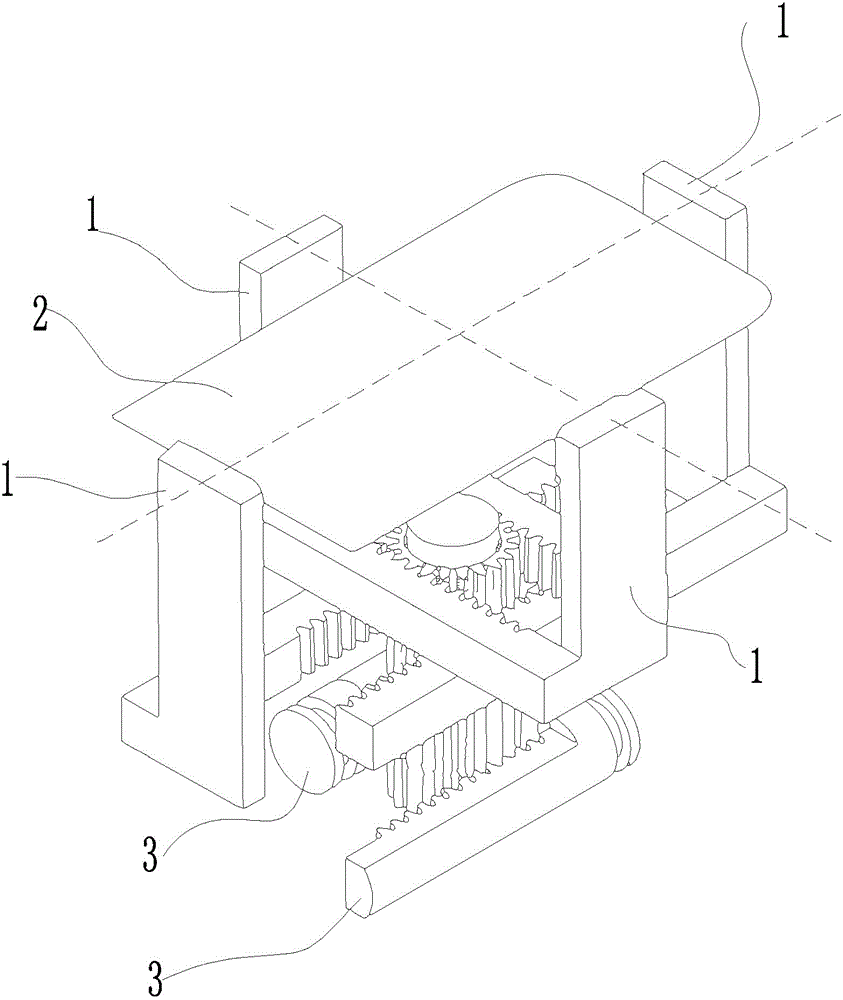
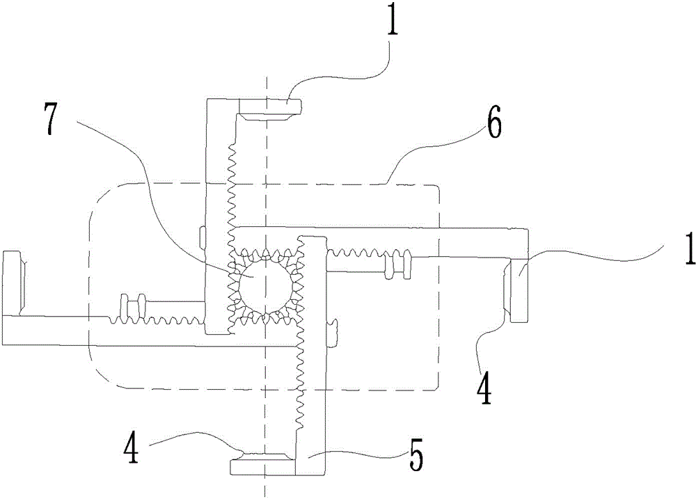
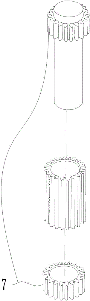
[0023] The reference signs in the drawings of the description include: pressing plate 1, door body 2, rack 3, buffer pad 4, under the pressing plate 5, projected area 6, gear shaft 7, return spring 9, motor output shaft 11, slider 10.

[0024] Such as figure 1 As shown, the door body 2 clamping device of the present invention includes a motor and a pressure plate 1 for pressing the door body 2. There are four pressure plates 1, which are respectively arranged at the four sides of the door body 2, wherein The side of the pressing plate 1 facing the adjacent side is a pressing surface, and the pressing surface is parallel to the adjacent side; the bottom 5 of the pressing plate is fixed with a rack 3 whose length direction is perpendicular to the pressing surface of the pressing plate 1; The gear shaft 7 arranged under the door body 2 and the racks 3 connected to the oppo...


PUM


Abstract

The invention relates to a door plate processing instrument, and particularly relates to a door body clamping device. The door body clamping device comprises a motor, four pressing plates in all, and a gear shaft, wherein the four resisting plates are used for pressing against a door body; one side of each pressing plate toward the adjacent side edge is a resisting surface; a rack of which the length direction is perpendicular to the resisting surface of each pressing plate is fixedly arranged below the pressing plate; the gear shaft is arranged below the door body; the racks which are respectively connected with the pressing plates with opposite positions are respectively arranged at two opposite sides of the gear shaft; the resisting plates and the racks form clamping function members; the clamping function members take the gear shaft as the center point and are in point symmetry distribution; the racks are meshed with the gear shaft; and the motor is fixedly connected with the lower end of the gear shaft or the motor is connected with the gear shaft through a transmission mechanism. The defect that the clamping device in the prior art cannot clamp from four surfaces is overcome; and the door body clamping device capable of automatically resetting is provided.

Description

technical field [0001] The invention relates to a door panel processing device, in particular to a door body clamping device. Background technique [0002] Before drilling or cutting the plate, it is necessary to clamp the plate so that it is in a relatively stable space, and then have corresponding cutters or drilling tools to process the plate. [0003] Current clamping equipment, such as a suspension U-shaped plate clamping and shaping device disclosed in Chinese patent CN102699142B, includes a base on which a first clamp and a second clamp are installed, and the clamping directions of the two clamps are parallel. The first clamp and the second clamp are respectively connected with the clamping driving device. It can clamp the two straight plates of the U-shaped plate to the required parallel state. Its two sets of clamping tools arranged symmetrically can move synchronously. [0004] However, a general door body has four sides in total and requires four-sided simultan...

Claims


Application Information

Patent Timeline
IPC IPC(8): B27C3/00B27C7/04B27C5/06B27C1/14
CPCB27C3/00B27C5/06
Inventor 刘侃
Owner CHONGQING OFAN DOOR IND
Why Eureka
Try Eureka