Plastic molding machine

A blister forming machine and forming part technology, applied in metal processing and other directions, can solve the problems of operator injury, trouble moving, inconvenient operation, etc., and achieve the effect of high degree of automation, labor saving and high processing efficiency.

Inactive Publication Date: 2015-03-25
赵立平
View PDF0 Cites 2 Cited by
  • Summary
  • Abstract
  • Description
  • Claims
  • Application Information

AI Technical Summary

Problems solved by technology

[0002] The traditional blister molding machine includes a body, a feeding device, a feeding device, a heating device, a forming device, a shearing device, and a feeding device. These devices are distributed on the body in a plane, resulting in a large and heavy structure of the whole machine. Occupying the site resources of the workshop, it is very troublesome to move and inconven

Method used


Image

  • Plastic molding machine
  • Plastic molding machine
  • Plastic molding machine

Examples


Example Embodiment

[0018] The technical solutions in the embodiments of the present invention will be clearly and completely described below in conjunction with the drawings in the embodiments of the present invention.
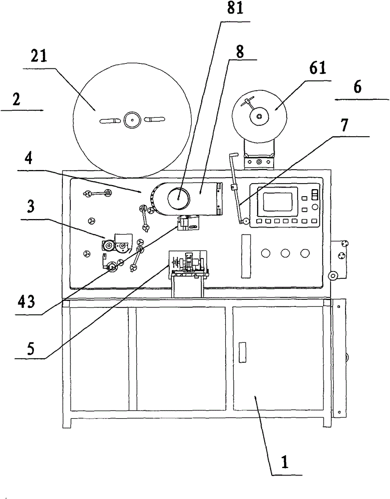
[0019] The invention provides a blister forming machine, such as figure 1 As shown in the structural schematic diagram, the blister molding machine has a compact structure, a high degree of automation, high processing efficiency, good safety, and rapid heat dissipation.
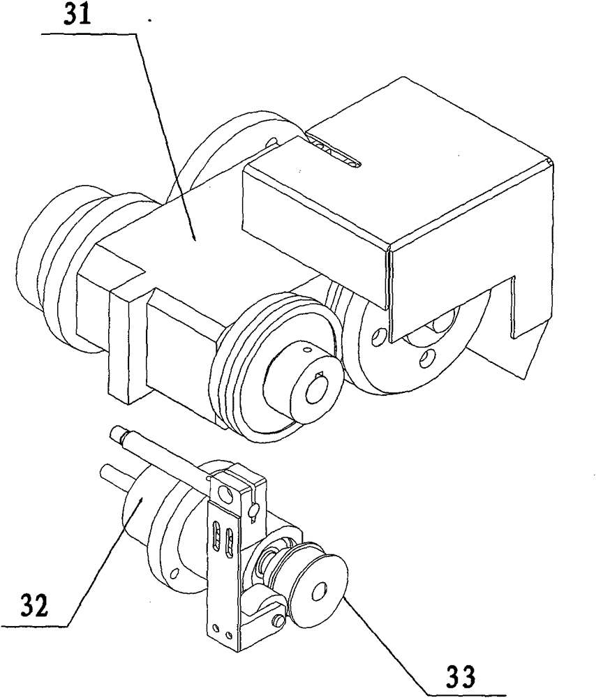
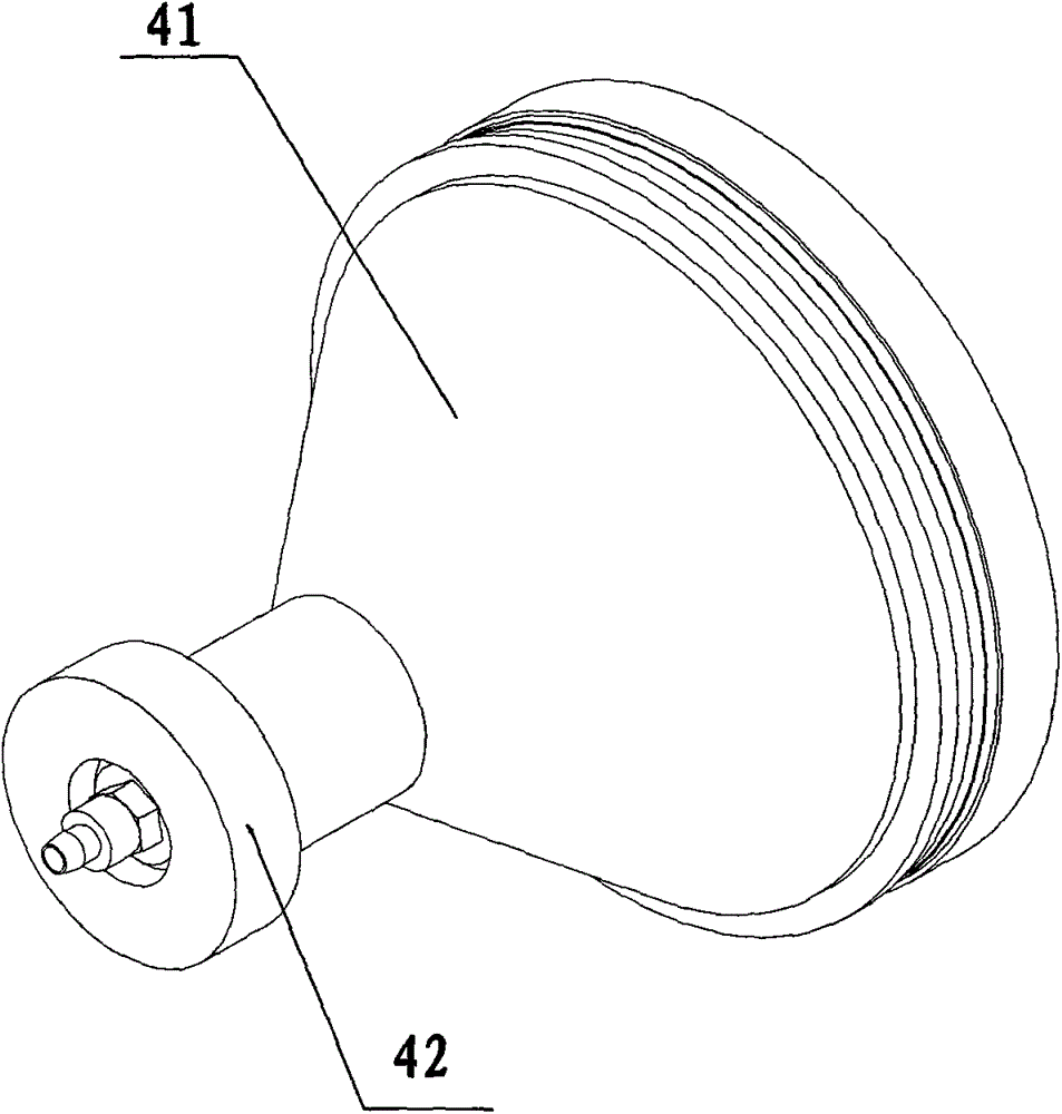
[0020] The blister molding machine includes a fuselage 1. The fuselage 1 is provided with a discharging section 2, a slitting section 3, a forming section 4, a punching section 5, and a receiving section 6 in sequence. The fuselage 1 is also provided with a conveyor The mechanism 7 is located between the above-mentioned components, the control devices connected to the above-mentioned components are all located in the fuselage, and the working parts of each component are located on the surface of the fuselage 1. This ...


PUM


Abstract

The invention discloses a plastic molding machine comprising a machine body, wherein a feeding part, a cutting part, a forming part, a punching part and a material receiving part are sequentially arranged on the machine body, a transmission mechanism is further arranged on the machine body, and all control devices located between the components and connected with the components are located in the machine body; the feeding part and the material receiving part are located at the top end of the machine body, the cutting part, the forming part and the punching part are distributed on the machine body, a protection cover is movably arranged at the outside of the forming part, a fan is arranged on the protection cover, and the plastic molding machine disclosed by the invention has the advantages of compact structure, good safety, fastness in heat dissipation and high processing efficiency.

Description

technical field [0001] The invention relates to a plastic-absorbing molding machine, in particular to a plastic-absorbing molding machine used in the electronic field. Background technique [0002] The traditional blister molding machine includes a body, a feeding device, a feeding device, a heating device, a forming device, a shearing device, and a feeding device. These devices are distributed on the body in a plane, resulting in a large and heavy structure of the whole machine. Occupying the site resources of the workshop, it is very troublesome to move and inconvenient to operate, which brings inconvenience to daily production; and because it needs to be heated during molding, the temperature is high, if there are no special protective measures, it is easy to cause injury to the operator, and, If there are no heat dissipation measures, it is easy to cause excessive local temperature and affect the service life of the machine. Contents of the invention [0003] In order...

Claims


Application Information

Patent Timeline
IPC IPC(8): B29C51/10B29C51/26B26F1/02
Inventor 赵立平
Owner 赵立平
Why Eureka
Try Eureka