Supercharge Your Innovation With Domain-Expert AI Agents!

Radio frequency type electromobile anti-theft alarm

A technology of anti-theft alarm and battery car, which is applied to bicycle accessories, devices to prevent theft of bicycles, transportation and packaging, etc. It can solve the problems that the alarm components cannot work and cannot block illegal personnel with unlocking skills, and achieve simple structure, low cost, Simple and fast effect

Inactive Publication Date: 2015-03-25
CHENGDU RUIYI INFORMATION TECH
View PDF6 Cites 2 Cited by
  • Summary
  • Abstract
  • Description
  • Claims
  • Application Information

AI Technical Summary

Problems solved by technology

[0002] With the maturity of the battery car technology, the battery car has become a common tool for people to travel, and the theft of the battery car has always been a social phenomenon that plagues people. There are many existing anti-theft measures, one is to lock the anti-theft, lock the motor, Tire locking is the most commonly used anti-theft method, but this type of anti-theft method still cannot stop illegal personnel with superb unlocking skills. The other type is electronic alarm technology, which uses a vibration sensor to detect the vibration of the car body and sends out an alarm. The alarm means is to connect the alarm component to the battery or the distributor of the battery car to continuously supply power to the alarm, and the alarm component will continue to work. Once the wire between the alarm component and the battery power supply is cut off, the alarm component will not work. Therefore The alarm component became a useless alarm component

Method used


Image

  • Radio frequency type electromobile anti-theft alarm
  • Radio frequency type electromobile anti-theft alarm
  • Radio frequency type electromobile anti-theft alarm

Examples


Embodiment 1

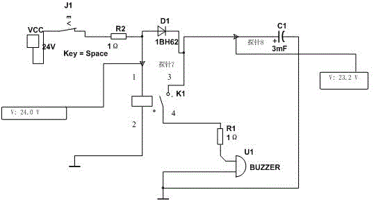
[0019] Such as figure 1 shown.

[0020] The radio frequency battery car anti-theft alarm includes resistor R2 and diode D1 connected in series in sequence, wherein the output terminal of resistor R2 is connected to the anode of diode D1, the input terminal of resistor R2 is connected to the positive pole of main power supply VCC, and an armature is normally closed The relay K1, the coil input terminal 1 of the relay K1 is connected to the anode of the diode D1, the coil output terminal 2 of the relay K1 is connected to the negative pole of the main power supply VCC, the armature input terminal 3 of the relay K1 is connected to the cathode of the diode D1, and the relay K1’s The armature output terminal 4 is connected in series with the buzzer U1, the negative pole of the buzzer U1 is grounded, at the same time, the negative pole of the diode D1 is connected to the capacitor C1 or the rechargeable battery, the cathode of the capacitor C1 or the negative pole of the rechargeable...


PUM


Abstract

The invention discloses a radio frequency type electromobile anti-theft alarm which comprises a resistor R2 and a diode D1. The output end of the resistor R2 is connected with the anode of the diode D1. The input end of the resistor R2 is connected with the positive pole of a main power source VCC. The radio frequency type electromobile anti-theft alarm further comprises a relay K1. The coil input end 1 of the relay K1 is connected with the anode of the diode D1. The coil output end 2 of the relay K1 is connected with the negative pole of the main power source VCC. The armature input end 3 of the relay K1 is connected with the cathode of the diode D1. The armature output end 4 of the relay K1 is connected with a buzzer U1 in series. The negative pole of the diode D1 is connected with a capacitor C1 or a charging battery. The anti-theft alarm further comprises a vibration alarm apparatus assembly. A wire between the vibration alarm apparatus assembly and the main power source is a main power source wire, and a wire between the input end of the resistor R2 and the positive pole of the main power source VCC is the same wire as the main power source wire. The radio frequency type electromobile anti-theft alarm has the advantage that an alarm can be given out quickly after the main power source wire is intercepted.

Description

technical field [0001] The invention relates to anti-theft alarm technology, in particular to a radio-frequency anti-theft alarm for battery cars. Background technique [0002] With the maturity of the battery car technology, the battery car has become a common tool for people to travel, and the theft of the battery car has always been a social phenomenon that plagues people. There are many existing anti-theft measures, one is to lock the anti-theft, lock the motor, Tire locking is the most commonly used anti-theft method, but this type of anti-theft method still cannot stop illegal personnel with superb unlocking skills. The other type is electronic alarm technology, which uses a vibration sensor to detect the vibration of the car body and sends out an alarm. The alarm means is to connect the alarm component to the battery or the distributor of the battery car to continuously supply power to the alarm, and the alarm component will continue to work. Once the wire between...

Claims


Application Information

Patent Timeline
Patent Type & Authority Applications(China)
IPC IPC(8): B62H5/20
CPCB62H5/20
Inventor 任佳袁祖斌
Owner CHENGDU RUIYI INFORMATION TECH
Features
  • R&D
  • Intellectual Property
  • Life Sciences
  • Materials
  • Tech Scout
  • Unparalleled Data Quality
  • Higher Quality Content
  • 60% Fewer Hallucinations
Learn More