Automatic roll discharging and core feeding device and automatic roll discharging and core feeding method

An automatic unloading and rewinding shaft technology, which is applied in the direction of winding strips, transportation and packaging, thin material processing, etc., can solve the problems of long time consumption, high labor intensity of workers, and low degree of automation, so as to reduce labor intensity and structure Simple and ingenious, highly customized effect

Active Publication Date: 2015-03-25
GUANGDONG JINMING MACHINERY
View PDF5 Cites 9 Cited by
  • Summary
  • Abstract
  • Description
  • Claims
  • Application Information

AI Technical Summary

Problems solved by technology

[0004] The above-mentioned working method of unloading and loading cores has the following dis

Method used


Image

  • Automatic roll discharging and core feeding device and automatic roll discharging and core feeding method
  • Automatic roll discharging and core feeding device and automatic roll discharging and core feeding method
  • Automatic roll discharging and core feeding device and automatic roll discharging and core feeding method

Examples


Embodiment 1

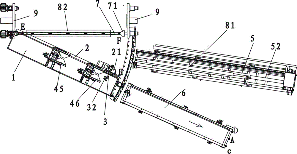
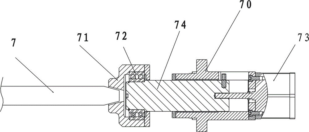
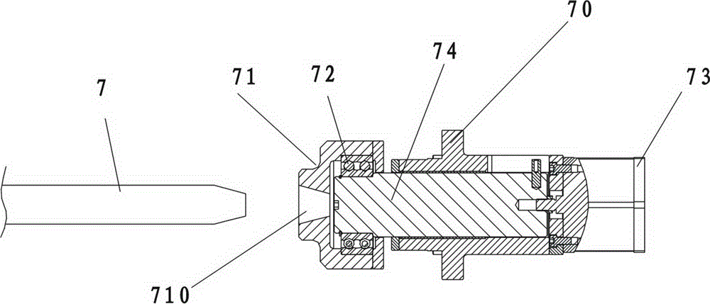
[0061] figure 1 As shown, the automatic unwinding core device includes a frame 9, a rewinding shaft 7, two ends of the rewinding shaft 7 are provided with a rewinding shaft support 70, 75, and the rewinding shaft 7 is rotatably (autorotated) mounted on the rewinding shaft support . figure 1 , figure 2 , image 3 Shown, wherein the first winding shaft support 70 ( figure 1 The support on the right side of the middle) is provided with a shaft sleeve 71, the inner cavity 710 of the shaft sleeve has a taper, the shaft sleeve 71 is axially movable and installed on the frame, and the winding shaft end on the same side as the shaft sleeve 71 department( figure 1 middle right end) is also provided with a corresponding taper; the frame is also provided with a shaft sleeve driving mechanism that drives the shaft sleeve to move axially. Telescopic link 74, telescopic link 74 and axle sleeve 71 are axially fixedly connected together by bearing 72, and telescopic link 74 and axle sle...

Embodiment 2

[0073] An automatic unwinding and coreing method, which adopts the automatic unloading and coreing device of the first embodiment, and includes the following steps in sequence: (1), the winding shaft 7 drives the paper core to rotate, and the plastic film is wound up to implement normal winding; roll to form a film volume 82; during normal winding, the winding shaft 7 is in the winding position, such as figure 1 As shown, the sliding support 21 is located at the far-center end of the swing support 1. From the horizontal projection position, the horizontal guide rail 2 is at a position forming a horizontal angle of 30° with the central axis of the winding shaft; Spare paper core tube 81; two support roller bearings 41 are in the low position of its vertical movement stroke (that is, the middle and lower part of vertical guide rail 42), the end of the swing arm and the small roller are in the low position of its swing stroke around the swing arm swing shaft 30, like figure 1 , ...


PUM


Abstract

The invention discloses an automatic roll discharging and core feeding device. A first rolling shaft support is provided with a shaft sleeve with an inner cavity with a taper angle, and the shaft sleeve is movably installed on a rack in the axial direction. A second rolling shaft support is provided with a vertical rotating shaft in a matched mode and is installed on the rack in a horizontal swinging mode through the vertical rotating shaft. A swinging support is horizontally installed below a rolling shaft in a swinging mode. The swinging support is provided with a horizontal guide rail, a sliding support and a sliding support driving mechanism. The horizontal guide rail is fixedly installed on the swinging support and swings along with the swinging support, and the sliding support driving mechanism can drive the sliding support to horizontally move along the horizontal guide rail. A swing arm is installed on the sliding support in a vertical swinging mode. A trundle is installed at the tail end of the swing arm, and the swinging support is provided with a left riding wheel and a right riding wheel. According to the automatic roll discharging and core feeding device, roll discharging and core feeding procedures can be automatically finished, the labor intensity of workers is relieved, and the time taken for the roll discharging and core feeding procedures is saved. The invention further provides an automatic roll discharging and core feeding method.

Description

technical field [0001] The invention belongs to the technical field of film production process winding, and in particular relates to an automatic unloading and core-setting device and an automatic unloading and core-setting method. Background technique [0002] After the film is produced, it is usually wound up into a coil using a winding device. During the winding process, the paper core tube sleeved on its outer periphery can be driven by the winding shaft to rotate continuously, so as to continuously roll up the film material, and the winding shaft can be an air expansion shaft. When the winding reaches the set length and the film roll reaches the set diameter, the film roll (together with the paper core) needs to be pulled out from the winding shaft. This process is called "unloading". After the unloading is completed, it is necessary to put the new spare paper core on the winding shaft and fix the end of the winding shaft. This process is called "core". [0003] In or...

Claims


Application Information

Patent Timeline
IPC IPC(8): B65H19/30
CPCB65H19/305
Inventor 何二君陈俊鸿温佳彬
Owner GUANGDONG JINMING MACHINERY
Why Eureka
Try Eureka