Elevator traction steel belt testing method and device

A technology of traction steel belt and elevator traction, which is applied in the field of elevators, can solve the problems of complex measurement mechanism, difficult measurement, low efficiency, etc., and achieve the effect of intuitive load force and improved test efficiency

Inactive Publication Date: 2015-03-25
GUANGZHOU GUANGRI ELEVATOR IND
View PDF9 Cites 5 Cited by
  • Summary
  • Abstract
  • Description
  • Claims
  • Application Information

AI Technical Summary

Problems solved by technology

Its efficiency is low, each up and down movement can only be tested once, and the bending test can only be performed on a certain point of the plate or strip product in one direction. Said that the single-direction bending experiment is not enough to simulate its real use environment
On the other hand, it is often impossible to know how much load force the existing testing device exerts on the test sample. The load force is the downward pressure exerted by the test head or the rotating eccentric wheel. It is difficult to measure and the measuring mechanism is relatively complicated.

Method used


Image

  • Elevator traction steel belt testing method and device
  • Elevator traction steel belt testing method and device

Examples


Embodiment 1

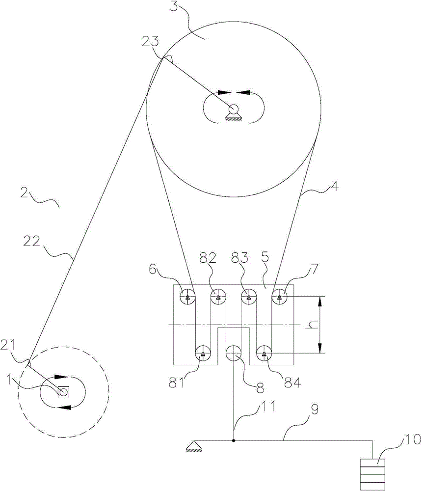
[0026] In this example, if figure 1 As shown, the device includes: a motor 1 . A crank rocker mechanism 2 linked with the motor 1 . The driving wheel 3 is connected with the crank rocker mechanism 2, so that the rotation of the motor is converted into the reciprocating rotation of the driving wheel, thereby driving the traction steel belt 4 to be tested to reciprocate. Five pulleys 81, 82, 8, 83, 84 are located below the drive pulley 3, arranged in waves in two rows and installed on the pulley mounting plate 5, wherein the pulley 8 in the middle is a movable pulley, and the others are fixed pulleys. pulley. The pulley mounting plate 5 is provided with a plurality of pulley mounting holes, and the pulley mounting holes are vertical elongated holes for adjusting the vertical position of the pulley. Wrap angle adjustment wheels 6, 7 are respectively arranged on both sides of the pulleys 81, 84 to ensure that the wrap angle of the pulleys on the outermost two sides is 180°. Th...

Embodiment 2

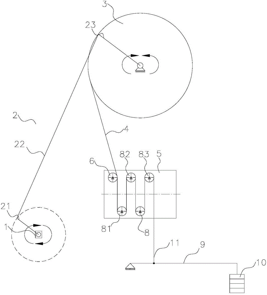
[0032] like figure 2 As shown, the driving wheel 3 is located above the pulleys 81 , 82 , 8 , 83 . Pulleys 81, 82, 8, and 83 are fixed pulleys, which are respectively installed on the vertical strip holes of the pulley mounting plate 5, and the outside of the pulley 81 is also provided with an angle adjustment wheel 6.

[0033] The traction steel belt 4 to be tested has a long strip structure, and the head end is fixed on the driving wheel 3. After the middle section passes through the wrapping angle adjustment wheel 6, the front and back sides go around the pulleys 81, 82, 8, 83 in sequence. The lead steel belt 4 bypasses the last pulley 83 from above, and the counterweight mechanism is directly fixed on the tail end of the lead steel belt 4 to be tested to apply a load force to it, including a lever 9 and a weight 10, and one end of the lever 9 is fixed , the other end is equipped with a weight 10, and the middle part is suspended on the tail end of the traction steel belt...


PUM


Abstract

The invention discloses an elevator traction steel belt testing method and device. The front side and the back side of a traction steel belt to be tested sequentially pass through two or more belt wheels, certain load force is applied to the traction steel belt to be tested through a counter weight mechanism, a driving wheel is driven through a power source and a transmission mechanism so that the traction steel belt to be tested can be driven to continuously move along the belt wheels, when a certain point of the traction steel belt to be tested passes through one belt wheel each time, bending testing is completed once, and therefore finally, the traction steel belt to be tested with bend testing performed for needed times can be obtained. According to the method and device, testing efficiency is improved, when the power source rotates once, bending testing is performed on the front side and/or the back side of the traction steel belt to be tested at least twice, testing efficiency is greatly improved, the front side and the back side can be tested at the same time, the testing condition can more approach the real using environment, the load force is directly applied to the traction steel belt to be tested through the counter weight mechanism, the magnitude of the load force can be more visualized, and the requirement for tension of the traction steel belt within different ranges can also be met.

Description

technical field [0001] The invention relates to the field of elevators, in particular to a test method and device for elevator traction steel belts. Background technique [0002] As a new elevator technology, the traction steel belt has been gradually promoted and used, but because the steel wire rope contained in this kind of traction steel belt is very small, its diameter is generally less than 2.5mm, and the elevator standard GB7588 stipulates that the diameter of the elevator steel wire rope cannot Less than 8mm, in order to popularize and use the new technology of traction steel belt, it is necessary to conduct a life test on it, so as to compare with the life of the steel wire rope commonly used in elevators, to ensure that the use of traction steel belt is equal to the use of ordinary elevator steel wire rope in terms of safety effective. For this reason, it is necessary to design a set of test equipment for the life of the traction steel belt in order to carry out t...

Claims


Application Information

Patent Timeline
Patent Type & Authority Applications(China)
IPC IPC(8): B66B5/00
CPCG01N3/34
Inventor 侯应浩贺云朗
Owner GUANGZHOU GUANGRI ELEVATOR IND
Why Eureka
Try Eureka