A new type of slewing support device for pile-wound crane

A technology of slewing bearings and cranes, which is applied in the direction of cranes, etc., can solve the problems of large design of slewing shafts and bushings, difficulty in maintenance and overhaul, and increased manufacturing costs, and achieve the effects of simple appearance, low cost, compact and unique structure

Active Publication Date: 2017-04-12
NANTONG RAINBOW HEAVY MACHINERIES
View PDF7 Cites 0 Cited by
  • Summary
  • Abstract
  • Description
  • Claims
  • Application Information

AI Technical Summary

Problems solved by technology

For conventional roller slewing heavy cranes (such as floating cranes), a set of rotary shaft structure is designed at the slewing center of the crane base, and then a set of slewing sleeves are designed at the lower part of the slewing platform to cover the rotary shaft of the base. Pile-encircling cranes still adopt a similar design, and the rotary shaft and bushing must be designed to be quite large (at least larger than the pile leg holes). This will bring complicated manufacturing processes, greatly increase manufacturing costs, and make subsequent maintenance and repairs more difficult. is difficult to carry out

Method used


Image

  • A new type of slewing support device for pile-wound crane
  • A new type of slewing support device for pile-wound crane
  • A new type of slewing support device for pile-wound crane

Examples


Embodiment Construction

[0015] In order to deepen the understanding of the present invention, the present invention will be further described below in conjunction with the embodiments and accompanying drawings. The embodiments are only used to explain the present invention and do not constitute a limitation to the protection scope of the present invention.

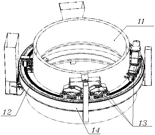
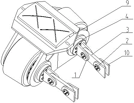
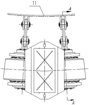
[0016] A specific embodiment of a new type of slewing support device for a pile-wrapping crane according to the present invention, such as figure 1 The shown slewing support device includes multiple sets of wheel sets, such as Figure 2 to Figure 4 Each set of wheel groups shown includes a wheel group bracket 9 and two wheels 6, and the two wheels 6 are installed inside the wheel group bracket 9 through two wheel shafts 5. Between each wheel 6 and the wheel shaft 5, two adjustment The core roller bearing 8 is assembled, the end of the wheel shaft 5 away from the rotating center cylinder 11 is fixed with the gland 7, and the end close to the rotat...


PUM


Abstract

The invention relates to a novel rotary supporting device of a pile winding type crane. The rotary supporting device comprises a plurality of wheel sets, wherein each wheel set comprises a wheel set bracket and two wheels; the two wheels are mounted in each wheel set bracket by two wheel shafts; each wheel and each wheel shaft are assembled by two alignment roller bearings; one end of each wheel shaft is fixed by a pressing cover and the other end of each wheel shaft is fixed by a connection pressing cover; two first lug plates are welded on each connection pressing cover and are connected with a connection plate by connection pin shafts; the other end of each connection plate is connected with second pole plates by connection pin shafts; and the second pole plates are welded on a barrel wall of a crane rotary platform. The novel rotary supporting device of the pile winding type crane has the advantages of compact structure, low cost, stability and reliability in operation and convenience for installation and maintenance.

Description

technical field [0001] The invention relates to a slewing support device, in particular to a new slewing support device of a pile-wrapping crane. Background technique [0002] At present, in order to increase the stability and lifting capacity of the crane operation on the offshore platform or crane ship operating on the sea, the platform or crane ship is designed with three or more jacking fixed platforms or crane ships. Because the legs occupy a large part of the space on the ship, in order to save deck space, large-tonnage cranes are designed and installed directly on the legs, and the crane rotates around the center of the legs, so the crane is called a slewing crane. . The lifting load of the pile-wound crane is generally more than several hundred tons, which belongs to the heavy-duty crane. Since a leg hole with a diameter of more than 5 meters needs to be opened in the slewing center of the slewing crane, a large amount of internal space of the crane itself is occup...

Claims


Application Information

Patent Timeline
IPC IPC(8): B66C23/84
CPCB66C23/84
Inventor 关德壮玉艳军
Owner NANTONG RAINBOW HEAVY MACHINERIES
Why Eureka
Try Eureka