Fixing end of steel support

A fixed end, steel support technology, applied in water conservancy projects, artificial islands, excavation, etc., can solve problems such as small support area, deformation, and decreased support force

Inactive Publication Date: 2015-03-25
CHANGZHOU YINBAO NICKEL NETWORK
View PDF0 Cites 0 Cited by
  • Summary
  • Abstract
  • Description
  • Claims
  • Application Information

AI Technical Summary

Problems solved by technology

[0003] The existing steel supports generally connect a flat plate at the end of the steel structure, and support the side wall of the foundation pit through the plane of the plate. The support force is reduced or deformed. Due to the difference in the foundation pit, different steel structures need to be replaced and used, and the versatility is poor.

Method used


Image

  • Fixing end of steel support
  • Fixing end of steel support
  • Fixing end of steel support

Examples


Embodiment Construction

[0017] The present invention will be further described below in conjunction with the accompanying drawings and specific embodiments.

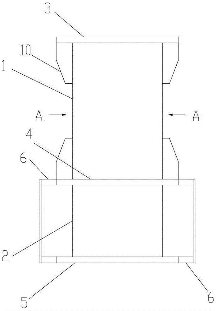
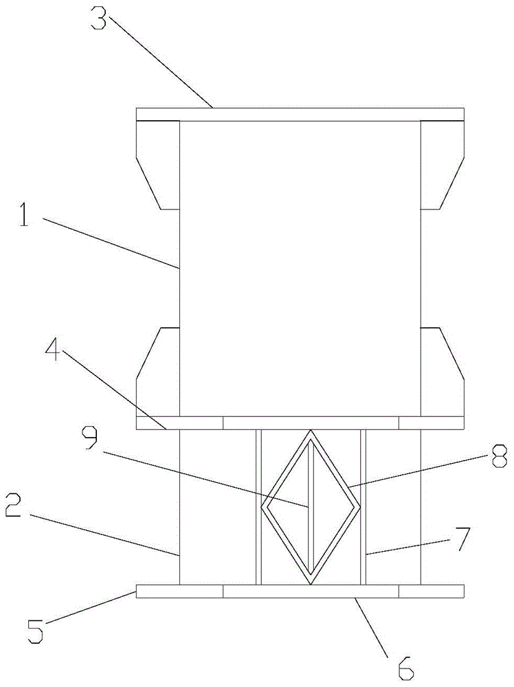
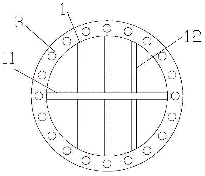
[0018] Such as Figure 1 to Figure 3 , the fixed end of the steel support, including the steel pipe body 1 and the connecting section 2, the two ends of the steel pipe body 1 are respectively connected with the first flange 3 and the second flange 4, and a central reinforcing plate is also welded in the steel pipe body 1 11 and the inner reinforcing plate 12 perpendicular to the center reinforcing plate 11, the connecting section 2 is connected with the second flange 4, the bottom of the connecting section 2 is connected with a bottom plate 5 having a diameter larger than the connecting section 2, and the two sides of the connecting section 2 The second flange 4 on the side and the bottom plate 5 are symmetrically provided with parallel elongated plates 6 , and a plurality of mutually parallel support plates 7 are arranged between the elongated...


PUM


Abstract

The invention relates to a fixing end of a steel support. The fixing end comprises a steel tube body and a connecting section. A first flange and a second flange are connected to the two ends of the steel tube body respectively, a central reinforcing plate and an inner reinforcing plate perpendicular to the central reinforcing plate are further welded in the steel tube body, the connecting section is connected with the second flange, a bottom plate is connected to the bottom of the connecting section, the diameter of the bottom plate is large than the diameter of the connecting section, lengthening plates are symmetrically arranged on the second flange and the bottom plate which are arranged on the two sides of the connecting section, a plurality of parallel supporting plates are arranged between the lengthening plates, and a diamond reinforcing plate is further arranged between the supporting plates. The fixing end of the steel support has the advantages of being capable of improving the stress state, stable in structure and the like.

Description

technical field [0001] The invention relates to the technical field of metal components, in particular to a fixed end of a steel support. Background technique [0002] The foundation pit is a temporary well excavated for the foundation of the building. The foundation pit is a temporary project, and its function is to provide a space for the foundation masonry to be carried out according to the position specified by the design. Generally, foundation pits are excavated in existing foundations, such as building subway passages under the road, or excavating a subway entrance and exit on the road surface. The foundation pits formed in this way generally need to be supported by steel structures during construction. , especially to support the two sides of the foundation pit to prevent the side of the foundation pit from collapsing, and the steel structure support can also support and fix the concrete pouring on the wall of the foundation pit, so the steel support structure is used...

Claims


Application Information

Patent Timeline
IPC IPC(8): E02D17/04E02D17/20E02D29/02
CPCE02D17/04E02D2300/0031
Inventor 高翔
Owner CHANGZHOU YINBAO NICKEL NETWORK
Why Eureka
Try Eureka