Electro-hydraulic servo valve

A technology of electro-hydraulic servo valve and spool, applied in the direction of servo motor components, valve details, multi-way valves, etc., can solve the problems of structural strength test, unreliable structural strength and sealing, and pressure increase of spring tube of electro-hydraulic servo valve , to achieve the effect of simple processing, reduced shape and position tolerance, and stable performance

Inactive Publication Date: 2015-03-25
JINCHENG NANJING ELECTROMECHANICAL HYDRAULIC PRESSURE ENG RES CENT AVIATION IND OF CHINA
View PDF5 Cites 15 Cited by
  • Summary
  • Abstract
  • Description
  • Claims
  • Application Information

AI Technical Summary

Problems solved by technology

[0003] The existing electro-hydraulic servo valve is generally a two-stage electro-hydraulic servo valve, because the electro-hydraulic servo valve is a precision servo control component, which not only includes mechanical parts, but also includes electrical components and magnetic components. In order to ensure its normal operation, often The cover is used to isolate these components from the outside air. Such a cover can have a good sealing effect under atmospheric pressure or at a lower pressure, but in the deep water and deep sea high pressure environment, it will cause damage to the external air. Under the action of high pressure, the structural strength and sealing are unreliable
Moreover, in a general hydraulic servo system, the pressure in the overflow chamber inside the electro-hydraulic servo valve is basically kept at a constant low value, while in deep water and deep sea environment, the system supply and return oil pressure goes down with the operating equipment As the depth increases, the pressure in the overflow chamber of the electro-hydraulic servo valve increases with the increase of the submerged depth of the operating equipment, which also causes a sharp increase in the internal pressure of the spring tube, the key component of the electro-hydraulic servo valve, and its structural strength will also be severely tested

Method used


Image

  • Electro-hydraulic servo valve
  • Electro-hydraulic servo valve
  • Electro-hydraulic servo valve

Examples


Embodiment Construction

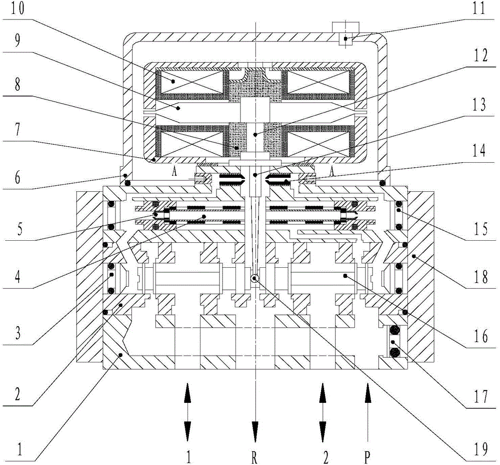
[0022] The present invention will be further described in detail through specific embodiments below. see Figure 1 ~ Figure 4 .

[0023] Such as figure 1 As shown, in the electro-hydraulic servo valve of the present invention, the upper cover (6) is provided with a torque motor, and the torque motor includes a magnetizer 7, a permanent magnet 8, an armature 9, a spring tube 12 and a baffle 13. A cavity is formed between the magnetizers 7 , and the permanent magnet steel 8 is located between the magnetizers 7 . The armature 9 is provided with a coil 10 , the spring tube 12 is connected with the armature 9 , one end of the baffle 13 is connected with the armature 9 , and the feedback rod 19 at the other end of the baffle 13 passes through the hole of the spring tube 12 .

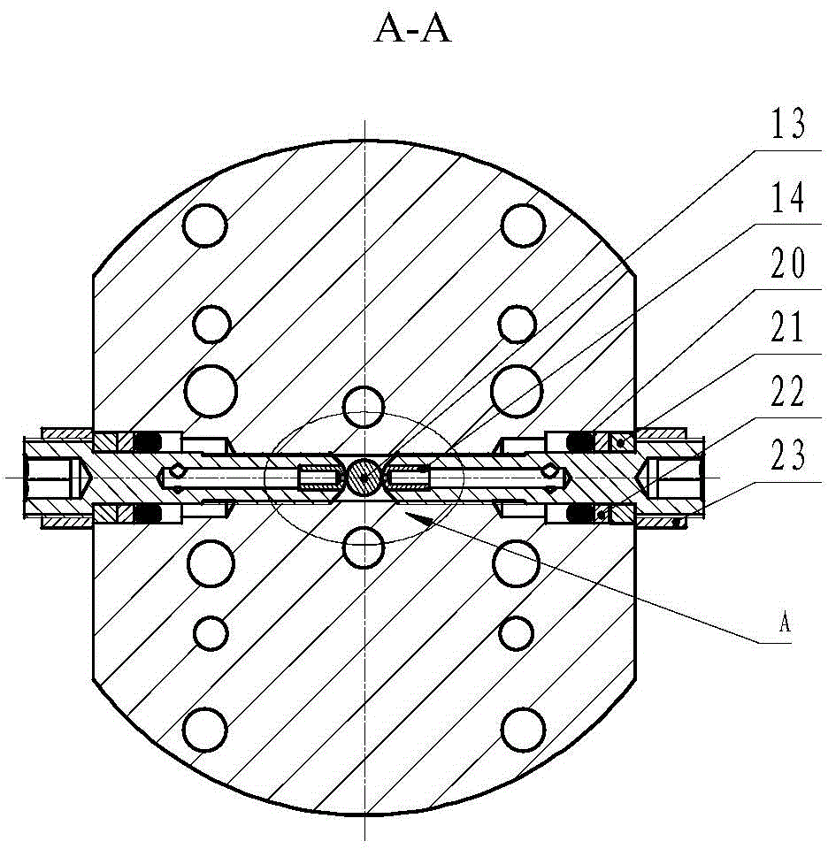
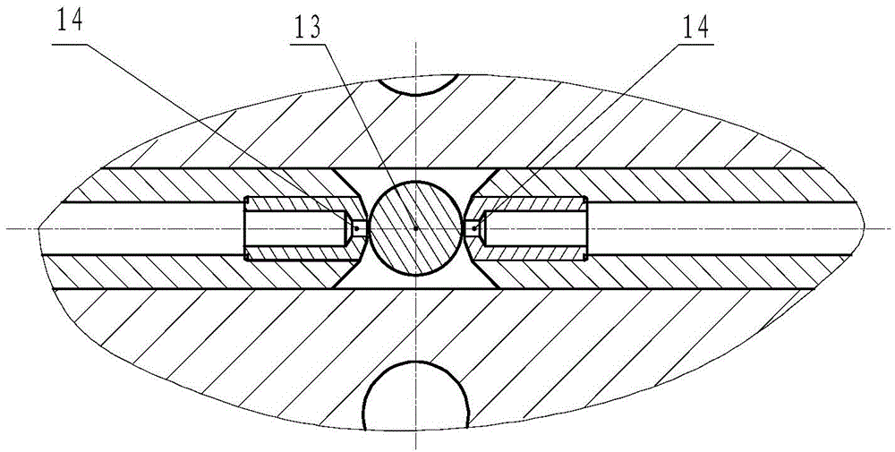
[0024] Described valve body is provided with the nozzle 14 that is positioned at the both sides of baffle plate 13, and the lower end of baffle plate 13 is a feedback rod 19 with ball head, and the valve co...


PUM


Abstract

The invention relates to a fluid control device, in particular to a novel electro-hydraulic servo valve. The novel electro-hydraulic servo valve comprises a shell (1), a valve element (7), a valve sleeve (2), a fixed throttling hole (5), a spraying nozzle (14), a coil (10), an armature (9), a spring pipe (12), a baffle (13), a feedback rod (19), permanent magnetic steel (8) and a pressure equalizing oil filter (11). The electro-hydraulic servo valve is characterized in that external pressure increased along with increase of submerged depth is used for equalizing pressure on the inner side and the outer side of the spring pipe (12) through the pressure equalizing oil filter (11), and the requirement for the structural strength of a cover body (6) and the spring pipe (12) is lowered. A changeable throttling device composed of the baffle (13) and the spraying nozzle (14) can increase the working stability of the electro-hydraulic servo valve and can also guarantee the driving capacity of the electro-hydraulic servo valve in deep-sea high-pressure high-viscosity fluid. The baffle (13) and the feedback rod (19) are integrally designed, and feedback moment is directly fed back to the baffle. The baffle (13) is a cylindrical baffle, and the machining difficulty of parts is lowered.

Description

technical field [0001] The invention belongs to the field of electro-hydraulic servo control engineering, and in particular relates to a deep-sea electro-hydraulic servo valve. Background technique [0002] The electro-hydraulic servo valve is a key component in the electro-hydraulic servo control system, and its performance has a great influence on the system characteristics. However, the existing electro-hydraulic servo valves are mainly used in ground equipment, aerospace, ships, and shallow water and shallow sea fields. At present, in the fields of offshore oil and gas exploration and development, most underwater operations have the characteristics of high pressure and heavy load, and as the operating equipment dives deeper, the environmental pressure is getting higher and higher, so the existing electro-hydraulic servo valve It can no longer meet the requirements for use in deep water and deep sea. Therefore, in order to meet the increasing operating requirements in hi...

Claims


Application Information

Patent Timeline
Patent Type & Authority Applications(China)
IPC IPC(8): F15B13/02F16K11/07F16K47/08
CPCF15B13/02F16K11/07
Inventor 陈元章孙牧
Owner JINCHENG NANJING ELECTROMECHANICAL HYDRAULIC PRESSURE ENG RES CENT AVIATION IND OF CHINA
Why Eureka
Try Eureka