Multistage pressure-limiting adjusting hydraulic buffer

A hydraulic buffer and adjustable technology, which is applied in the field of hydraulic buffers, can solve the problems of insufficient energy consumption, high acceleration, and unavoidable car crashes and fatalities, and achieve stable and uniform damping force, fast response, extended buffer stroke and collision the effect of time

Active Publication Date: 2015-03-25
HUNAN UNIV OF SCI & TECH
View PDF6 Cites 3 Cited by
  • Summary
  • Abstract
  • Description
  • Claims
  • Application Information

AI Technical Summary

Problems solved by technology

For the existing viscous damper, it is close to 1, and the damping force is approximately proportional to the speed, which will lead to high acceleration at the beginning of the collision and insufficient energy consumption in the later stage
It is precisely because of the above reasons that there is no buffer device installed at the rear of large trucks at present, and the baffles installed in it can hardly avoid the tragic situation of vehicle crash

Method used


Image

  • Multistage pressure-limiting adjusting hydraulic buffer
  • Multistage pressure-limiting adjusting hydraulic buffer
  • Multistage pressure-limiting adjusting hydraulic buffer

Examples


Embodiment Construction

[0021] The present invention will be further described below in conjunction with the accompanying drawings and embodiments.

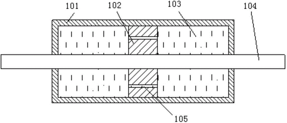
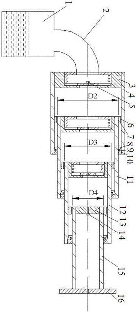
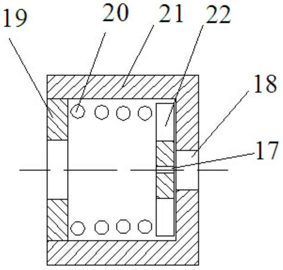
[0022] Such as figure 2 As shown, the present invention includes four-stage buffer mechanisms connected sequentially from left to right, and each stage buffer mechanism of the first three-stage buffer mechanisms includes a cylinder body, a pressure-limiting adjustable overflow valve 3, a sealing seat 8, a sealing ring 9 and The end cover 10, wherein the second buffer mechanism and the third buffer mechanism also include a guide ring 6; the fourth buffer mechanism includes a fourth cylinder 15, a screw plug, a screw, a pressure bearing plate 16 and a guide ring 6.

[0023] From left to right, the cross-sectional diameters of the buffer mechanism cylinders decrease successively, the left end of the fourth cylinder 15 is threadedly connected with the screw plug 14, and the outer wall of the left end of the fourth cylinder 15 is provided with a guide ring ...


PUM


Abstract

The invention discloses a multistage pressure-limiting adjusting hydraulic buffer comprising a plurality of buffer mechanisms connected in order from left to right. Each buffer mechanism comprises a cylinder block, a pressure-limiting adjusting overflow valve and a piston; the pressure-limiting adjusting overflow valve is fixed to the left of the cylinder block in a threaded manner. In every two adjacent buffer mechanisms, the left end of the cylinder block of the right one is hermetically connected to the right end of the cylinder block of the left one in a sleeving manner, the cylinder block of the right one can move relative to the cylinder block of the left one so as to serve as a piston for the left one; the pressure-limiting adjusting overflow valve of the leftmost one of the buffer mechanisms is connected with an oil tank through an oil pipe; the right end of the cylinder block of the rightmost one is connected with a bearing plate in a threaded manner. The multistage buffering and the pressure-limiting adjusting overflow valves are combined to form a constant-damping-force long-stroke buffer; buffering stroke and collision time are prolonged; power consumption for buffering is maximally reduced at the premise that maximum acceleration is lower than a designed value.

Description

technical field [0001] The invention relates to a hydraulic buffer, in particular to a multi-stage pressure-limiting adjustable hydraulic buffer. Background technique [0002] Automobile rear-end collision accidents on expressway often take place, and the dolly of fast travel rear-ends the large truck of slow speed travel, and the result of accident often causes the car crash of dolly. Existing automobile impact buffers can be divided into energy-consuming shock absorbers such as spring buffers, hydraulic buffers, and electromagnetic buffers. In order for the two vehicles approaching at high speed to release energy smoothly, the required resistance should not only be large and last for a long time, but also stable and controllable without being affected by speed changes. [0003] Viscous dampers are widely used in building structures and bridge structures for energy dissipation and vibration reduction, and their damping force is large. The structure of the viscous damper g...

Claims


Application Information

Patent Timeline
Patent Type & Authority Applications(China)
IPC IPC(8): F16F9/32F16F9/34
CPCF16F9/22F16F9/34F16F9/512
Inventor 禹见达刘力张福寿唐伊人
Owner HUNAN UNIV OF SCI & TECH
Why Eureka
Try Eureka