Solar cooker

A solar cooker and bottom plate technology, applied in the mechanical field, can solve the problems of many working links in the tracking system, limit the range of use of the cooker, increase the production cost of the product, etc., and achieve the effect of convenient use, simple structure and low production cost

Active Publication Date: 2015-03-25
HIMIN CLEAN ENERGY HLDG
View PDF4 Cites 7 Cited by
  • Summary
  • Abstract
  • Description
  • Claims
  • Application Information

AI Technical Summary

Problems solved by technology

[0004] Although this cooker can automatically adjust the placement angle of the reflector, the tracking system of the control box has many working links and complicated structure, which not only greatly increases the production cost of the product, makes the product price too high, and reduces the market competitiveness, but also makes this cooker The failure rate of the cooker will also increase, which increases the cost of after-sales service and reduces the user experience; in addition, the automatic adjustment is realized by controlling the rotation of the drive wheel. The cooker has certain requirements on the ground of the place of use, which also limits Range of use of cooking utensils
[0005] This shows that the above-mentioned existing solar cooker obviously still has defects in structure and use, and needs to be further improved urgently.

Method used


Image

  • Solar cooker
  • Solar cooker
  • Solar cooker

Examples


Embodiment 1

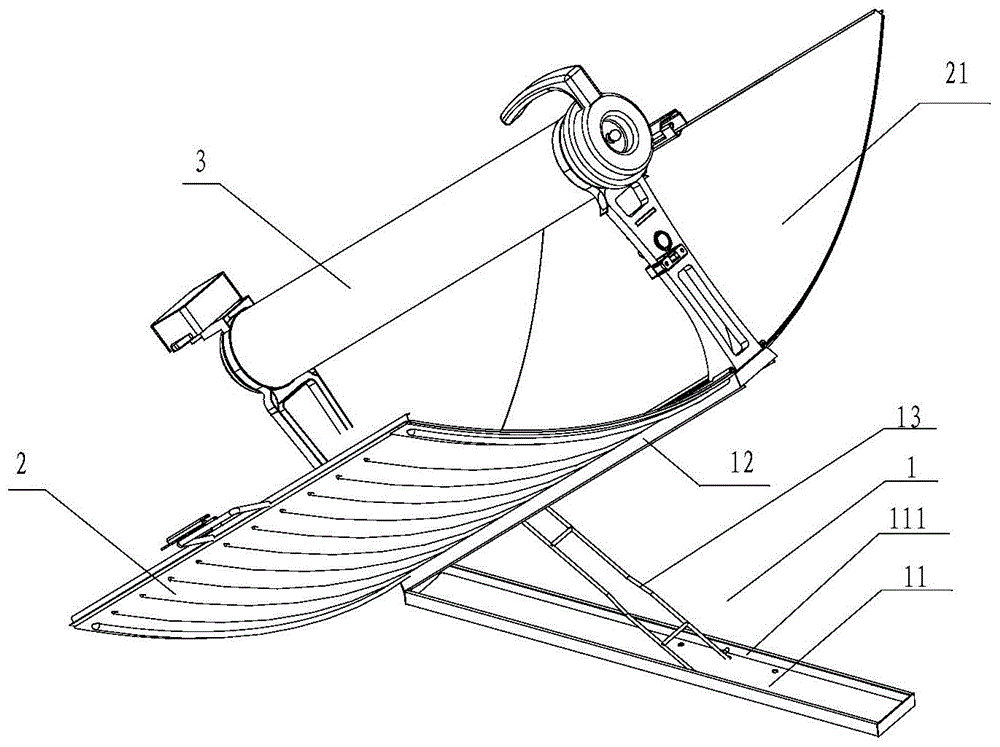
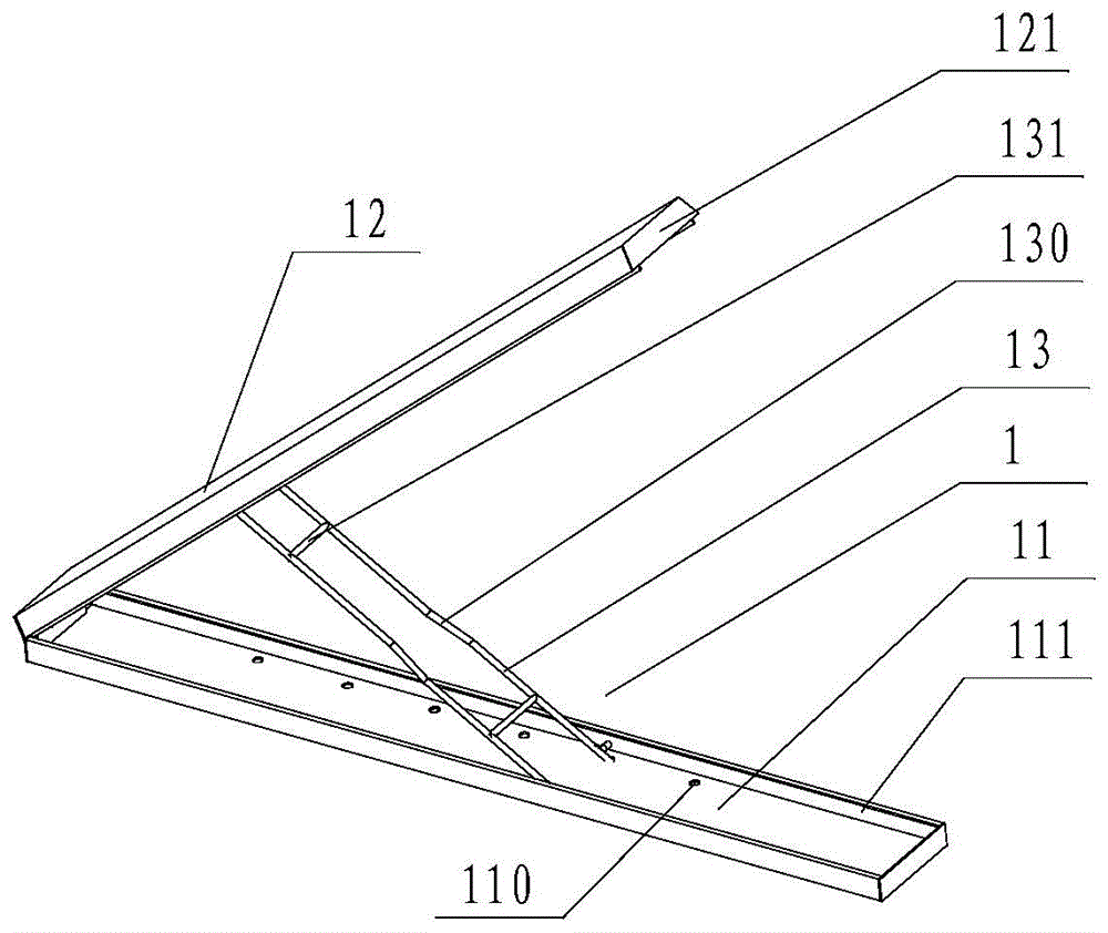
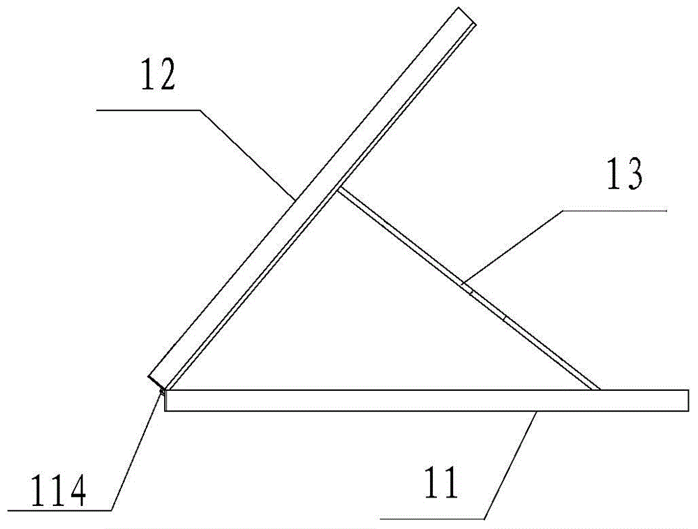
[0130] Embodiment 1 When in use, the fixed plate 221 is preferably fixed on the upper surface of the cooker cover plate 12 by bolts, and the two sides of the fixed plate 221 are fixed on the outer surface of the shell of the cooker by the rib plates connected by hinges, and the two shells of the cooker are respectively It is rotatably connected to both sides of the cover plate 12 of the cooker. When the shell of the cooking utensil is opened, the rib plate is opened together with the shell, and when it is opened to a certain set angle, the rib plate is fixed and kept at the set angle, so that the shell is also kept at this one Opening angle, in order to achieve gathering as much sunlight as possible, shining on the vacuum tube. The stiffener plate is fixed at a certain set angle. One, it can be limited by the structure of its hinge with the fixed plate 221, or it can be defined by the bottom surface of the L-shaped stiffener plate and the upper surface of the cooker cover plat...

Embodiment 2

[0138] When embodiment 2 is in use, since at least two sets of reinforcing plates are arranged on the two sides of the shell, and their length is equal to the length of the sides of the shell, it can not only bear the supporting force while maintaining the angle of the shell, but also can The shell can be kept without deformation, the two shells will not be dislocated when closed, and the use is convenient.


PUM


Abstract

The invention discloses a solar cooker and relates to the field of machinery. The solar cooker comprises a base, a vacuum tube, a fixing rack, a shell and a reflector. The base comprises a base plate, a cover plate and a support, wherein the cover plate is disposed on the base plate, one end of the cover plate is connected with one end of the base plate through a pin, the cover plate can rotate around the pin, and the support is disposed between the base plate and the cover plate and used for manually fixing the rotating angle of the cover plate. A heating cavity is arranged in the vacuum tube and used for cooking foods. The fixing rack is disposed on the cover plate. The vacuum tube is disposed on the fixing rack. The shell is disposed on two sides of the cover plate. The cover plate is movably connected with the shell. During a non-working state, the shell is closed, and during a working state, the shell is opened and positioned. The reflector is disposed on the inner surface of the shell and used for reflecting sunlight to the vacuum tube.

Description

technical field [0001] The invention relates to the mechanical field, in particular to a solar cooker. Background technique [0002] With the development of economy and science and technology, human beings have an increasing demand for energy, and the problem of energy shortage has attracted much attention; at the same time, with the continuous improvement of people's living needs and the development of industrial production, environmental pollution has become an issue that affects sustainable development. The biggest obstacle is the imminent development and utilization of environmentally friendly green energy. Solar energy is more and more favored by people because of its environmental protection, sustainability, richness, universality and other advantages. [0003] Although solar energy is widely used in hot water supply and photovoltaic power generation, and has made great contributions to environmental improvement; however, people are still further expanding the fields ...

Claims


Application Information

Patent Timeline
Patent Type & Authority Applications(China)
IPC IPC(8): F24J2/05F24J2/24F24J2/10F24J2/52F24J2/46F24S10/40F24S10/70F24S23/70
CPCF24S20/30F24S23/74F24S30/455Y02A40/926Y02B40/18Y02E10/47
Inventor 黄鸣倪伟跃杨青林赵吉芳刘俊义崔正军吕世炎陈洪晶孙延乐安洁王聪于家伍
Owner HIMIN CLEAN ENERGY HLDG
Why Eureka
Try Eureka