Solar water heater
A technology for solar water heaters and water tanks, which is applied to solar thermal power generation, solar thermal devices, heating devices, etc., can solve the problems of reducing the service life of solar water heaters, easy aging and deformation of polyurethane, and achieves simple structure, good thermal insulation effect, and easy processing. low cost effect
- Summary
- Abstract
- Description
- Claims
- Application Information
AI Technical Summary
Problems solved by technology
Method used
Image

Examples
Embodiment 1
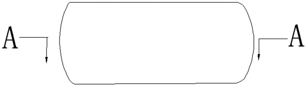
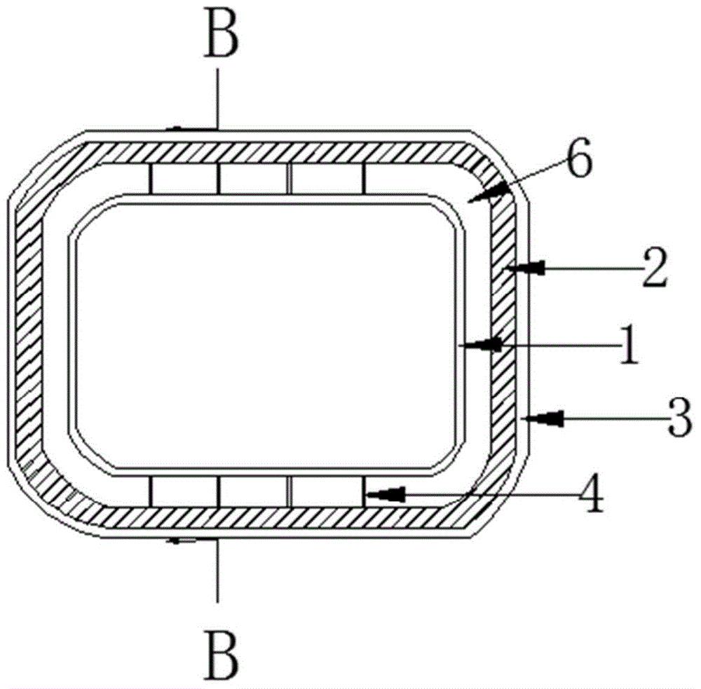
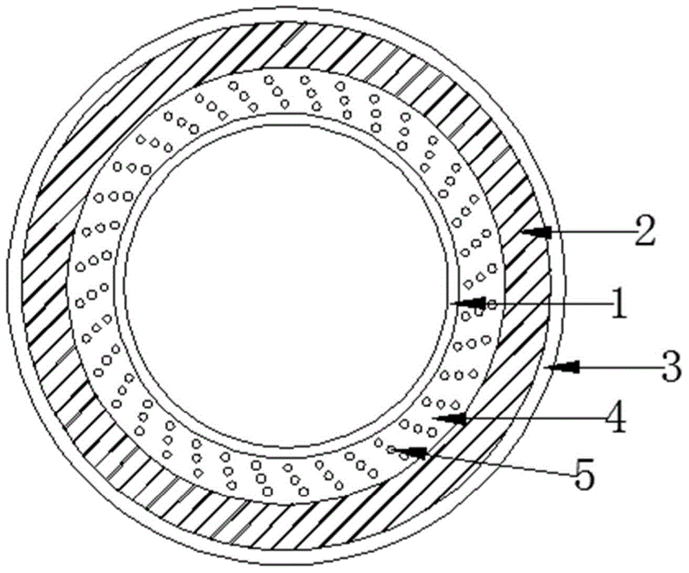
[0023] The present invention provides a kind of solar water heater, embodiment 1 is as figure 1 , figure 2 and image 3 As shown, including the heat preservation water tank, the heat preservation water tank is sequentially provided with an inner tank 1 made of stainless steel, a polyurethane insulation layer 2 and a water tank shell 3 made of color steel plates from the inside to the outside. The outer wall of the inner tank 1 is provided with 4 surrounding The baffle plate 4 of the inner tank 1 is provided with several through holes 5, a vacuum layer 6 is formed between the inner tank 1 and the polyurethane insulation layer 2, and the outer side of the polyurethane insulation layer 2 is closely bonded to the water tank shell 3. The setting of the baffle plate 4 in this embodiment can reduce the deformation of the polyurethane insulation layer 2, and the through hole 5 provided on the baffle plate 4 can facilitate vacuuming. The setting of the water tank shell 3 effectively...
Embodiment 2
[0025] The present invention provides a kind of solar water heater, embodiment 2 is as Figure 4 , Figure 5 and Image 6 As shown, it includes the heat preservation water tank. The heat preservation water tank is provided with an inner tank 1 made of stainless steel, a polyurethane insulation layer 2 and a water tank shell 3 made of galvanized sheet from the inside to the outside. The outer wall of the inner tank 1 is provided with 10 A baffle 4 surrounding the liner 1, the baffle 4 is provided with a number of through holes 5, a vacuum layer 6 is formed between the liner 1 and the polyurethane insulation layer 2, the outer side of the polyurethane insulation layer 2 is closely bonded to the water tank shell 3, and the polyurethane The inner side of the insulation layer 2 is connected with a 0.5mm thick stainless steel plate layer 7, and the vacuum layer 6 communicates with the outside atmosphere through a vacuum hole 8, and a sealing plug is filled in the vacuum hole 8. Th...
PUM
| Property | Measurement | Unit |
|---|---|---|
| Thickness | aaaaa | aaaaa |
Abstract
Description
Claims
Application Information