Regenerative combustion device

A combustion device and regenerative technology, applied in the direction of burner, combustion method, combustion type, etc., can solve the problems of large furnace impact, high furnace pressure, poor smoke exhaust, etc., to achieve huge energy saving potential, uniform temperature distribution, good heating effect

Inactive Publication Date: 2015-03-25
HUNAN BALING FURNACE ENERGY CONSERVATION
View PDF6 Cites 13 Cited by
  • Summary
  • Abstract
  • Description
  • Claims
  • Application Information

AI Technical Summary

Problems solved by technology

In this kind of regenerative combustion system with paired distributed burners, since the pipe space used to provide combustion-supporting gas for combustion is equal to the flue gas pipe space used for smoke exhaust, the combustion-supporting gas and fuel are mixed and burned to produce The volume of flue gas will increase, and the volume of flue gas under standard conditions is at least 1.1-1.3 times the volume of combustion-supporting gas. High voltage, unsafe state
The existing solution is to add an auxiliary flue to the furnace body to allow about 30% of the high-temperature flue gas to be discharged directly, but this will cause the total waste heat recovery rate of the flue gas to be only 50%-60%, and the exhaust gas temperature is too high Will directly affect the safe operation of environmental protection devices
[0004] Therefore, poor smoke exhaust, high furnace pressure, and low waste heat recovery rate of the total flue gas are one of the technical problems that have not yet been resolved in the current regenerative combustion technology.
[0005] On the other hand, in the existing regenerative combustion system with paired burners, the furnace pressure fluctuates greatly when reversing, and in severe cases, the impact on the furnace is relatively large, which affects the safe operation of the device

Method used


Image

  • Regenerative combustion device
  • Regenerative combustion device
  • Regenerative combustion device

Examples


Embodiment Construction

[0063] Embodiments of the present invention will be described in further detail below in conjunction with the accompanying drawings and examples, but those skilled in the art will understand that the following examples are only used to illustrate the present invention, and should not be considered as limiting the scope of the present invention.

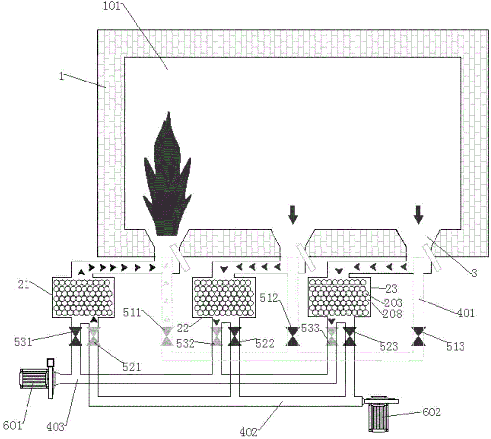
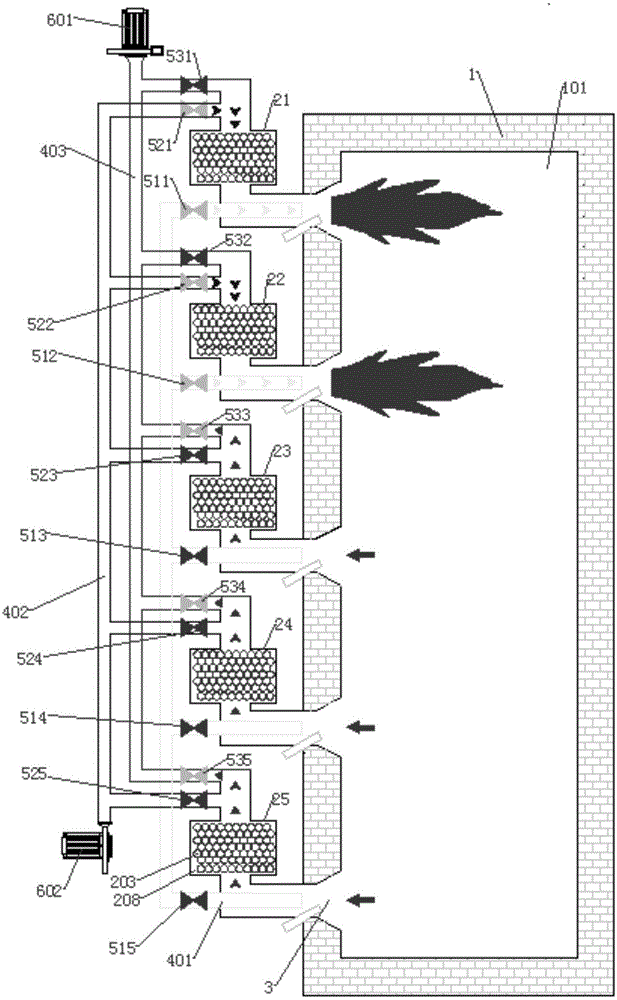
[0064] As a preferred embodiment of the present invention, such as figure 1 As shown, a regenerative combustion device in this embodiment includes a furnace body 1, a furnace 101 set in the furnace body 1, three regenerative burners 2, a gas pipeline 401, a combustion-supporting gas pipeline 402, The flue gas pipeline 403 and the reversing valve 5.

[0065] The furnace body 1 is not provided with an auxiliary pipe communicating with the furnace 101 for directly discharging the flue gas in the furnace, and has strict sealing.

[0066] Holes are opened on the furnace wall of the furnace 101 . The first regenerative burner 21, the seco...


PUM


Abstract

The invention relates to a regenerative combustion device. The regenerative combustion device comprises at least three regenerative combustors connected with a furnace hearth and a controller capable of controlling the regenerative combustors, the regenerative combustors are switched by the controller to be alternately used for combustion or smoke exhaust, and therefore the number of the regenerative combustors, used for smoke exhaust, of the device is larger than the number of the regenerative combustors, used for combustion, of the device at any time. Compared with the prior art, the regenerative combustion device is smooth in smoke exhaust, stable in furnace pressure, high in overall flue gas waste heat recovery rate and even in temperature distribution in a furnace, high-temperature low-nitrogen oxide combustion is achieved, more energy is saved, environmental protection is achieved better, and the device is safer.

Description

technical field [0001] The invention relates to a combustion device, in particular to a regenerative combustion device Background technique [0002] Industrial furnaces are the main energy-consuming equipment in industrial production, and the energy consumption accounts for 60% of the total industrial energy consumption. Therefore, the research on its energy-saving technology is of great significance. [0003] Existing industrial furnaces generally use regenerative combustion systems to recover and utilize the waste heat of flue gas. However, the regenerative combustion systems currently used at home and abroad are all arranged in pairs, that is, one group of regenerative burners is used for combustion, and the other group of the same number of regenerative burners is used for smoke exhaust, and the timing is reversed. The heat accumulator alternately stores and releases heat. In this kind of regenerative combustion system with paired distributed burners, since the pipe sp...

Claims


Application Information

Patent Timeline
Patent Type & Authority Applications(China)
IPC IPC(8): F27D19/00F27D17/00
CPCF23D23/00F23N5/00F23L2900/15022F27D17/004F27D99/0033F23L15/02F23N2237/02Y02E20/34Y02P80/15
Inventor 周绍芳
Owner HUNAN BALING FURNACE ENERGY CONSERVATION
Why Eureka
Try Eureka