Computing method of probe lifting heights of test probes of flying-probe tester

A flying probe testing machine and calculation method technology, which is applied to the parts of electrical measuring instruments, measuring electricity, measuring devices, etc., can solve the problems of reducing test efficiency, uneven clamping force, PCB deformation, etc. The effect of scraper probability

Active Publication Date: 2015-03-25
HANS CNC SCI & TECH
View PDF5 Cites 18 Cited by
  • Summary
  • Abstract
  • Description
  • Claims
  • Application Information

AI Technical Summary

Problems solved by technology

However, in the prior art, the movement of the probe is generally affected by the deformation of the PCB: 1. Since there are multiple processes in the manufacturing process of the PCB, and there are inevitably errors in each process, in addition, after transportation and storage, etc. Therefore, there is a certain deformation of the PCB itself; 2. The PCB to be tested is mechanically clamped in the middle of the equipment by the fixture for testing, and problems such as uneven clamping force will also cause deformation of the PCB
When the flying probe tester tests these PCBs with deformation problems, in order to avoid scratches on the PCB to be tested when the test probe moves in the X-Y plane, it is necessary to set the height of the test probe to the PCB to be tested more appropriately because: If the lift height of the test probe is too high, the test efficiency will be reduced; on the contrary, if the lift height of the test probe is too low, there may be scraper phenomenon (especially for large-area PCBs)

Method used


Image

  • Computing method of probe lifting heights of test probes of flying-probe tester
  • Computing method of probe lifting heights of test probes of flying-probe tester
  • Computing method of probe lifting heights of test probes of flying-probe tester

Examples


Embodiment Construction

[0023] Now in conjunction with the accompanying drawings, the preferred embodiments of the present invention will be described in detail.

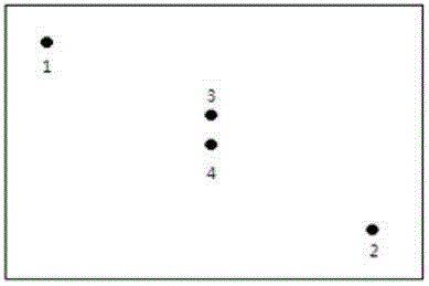
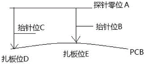
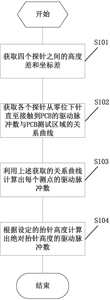
[0024] figure 1 Obtain position indications for the relationship curve test points of the calculation method of the needle lifting height in the present invention. figure 2 It is a schematic diagram of the position of the lower needle in the method for calculating the height of the needle raised in the present invention. image 3 It is a schematic flow chart of the method for calculating the needle lift height of the present invention.

[0025] see Figure 1 to Figure 3 , The present invention provides a method for calculating the lifting height of the test probe of a flying probe testing machine, which can take effective steps to reduce the probability of the probe scraper during the test while ensuring the test efficiency. The flying probe testing machine includes two probes for acting on the front of the PCB to be tested and two pro...


PUM


Abstract

The invention relates to a testing method of PCBs, in particular to a computing method of the probe lifting heights of test probes of a flying-probe tester. Each probe independently and rapidly moves under driving of a motor installed on the X-Y axis and makes contact with a corresponding welding point on a PCB to be tested under driving of a stepping motor in the Z direction for necessary electrical measurement. The computing method comprises the following steps that height differences and coordinate differences among the four probes are obtained; a relation curve between a PCB testing area and the number of drive pulses generated when each probe is fed from the zero position until the probe makes contact with the PCB is obtained; the number of drive pulses of each measurement point is worked out by utilization of the obtained relation curves; the number of drive pulses corresponding to the probe lifting height of each probe is worked out according to the set probe lifting height. The computing method can reduce the board scraping probability of the probes in the testing process under the condition of ensuring the testing efficiency.

Description

technical field [0001] The invention relates to a testing method for printed circuit boards, in particular to a testing method for printed circuit board testing equipment. Background technique [0002] The test probes of PCB (printed circuit board) test equipment (also known as flying probe tester) generally consist of two probes on the front of the PCB to be tested and two probes on the back of the PCB to be tested, a total of four probes . In the actual flying probe testing machine, the PCB to be tested is clamped by a fixture, and these probes can be driven by a motor installed on the X-Y axis to move quickly independently, and can be driven by a stepping motor in the Z direction to be connected with the test probe. The solder joints on the PCB make contact to make the necessary electrical measurements. In the testing process, it is generally required that the movement of the probe has the characteristics of high speed, high precision and low scratch. However, in the p...

Claims


Application Information

Patent Timeline
Patent Type & Authority Applications(China)
IPC IPC(8): G01B7/02G01R1/073
Inventor 张恂谭艳萍王星翟学涛杨朝辉高云峰
Owner HANS CNC SCI & TECH
Why Eureka
Try Eureka