Fast polarization detector and detecting method

A detector and polarization technology, which is applied in the field of fast polarization detector and detection, and can solve the problems of many components, large volume, and high requirements.

Active Publication Date: 2015-03-25
SHENZHEN GRADUATE SCHOOL TSINGHUA UNIV
View PDF7 Cites 27 Cited by
  • Summary
  • Abstract
  • Description
  • Claims
  • Application Information

AI Technical Summary

Problems solved by technology

However, most simultaneous polarization detectors have higher requirements for micro-processing technology, or have more components, larger volume, and higher cost.
And each device often corresponds to a variety of differ...

Method used


Image

  • Fast polarization detector and detecting method
  • Fast polarization detector and detecting method
  • Fast polarization detector and detecting method

Examples


Embodiment 1

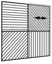
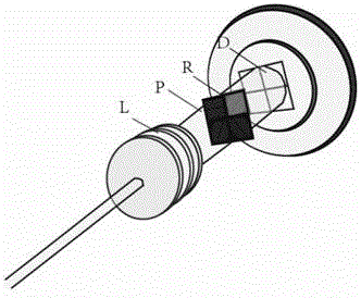
[0107] Take the polarization analyzer module including four polarizers and one wave plate as an example. At this time, it includes four polarization analyzer channels with different polarized light transmission directions. The incident light with different polarization states to be measured is projected to the On a four-quadrant detector or equivalent, the change in polarization state during this process is:

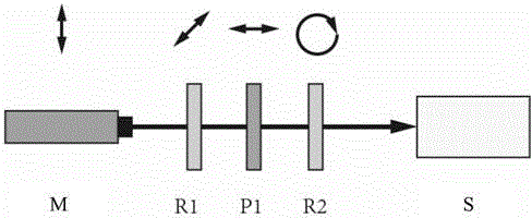
[0108] S out = M p M r ·S in

[0109] Among them, S in is the polarization state of the incident light, S out is the polarization state of the outgoing light on the surface of the four-quadrant detector, M p is the Mueller matrix of the polarizer, M r is the Mueller matrix of the wave plate, the above M p M r or M p is the transformation of the incoming Stokes vector to the outgoing Stokes vector, capable of measuring all polarization characteristics of the polarimeter. The final signal of the four-quadrant detector is the intensity signal of the light, which ...

Embodiment 2

[0138] The difference from the previous embodiment is that the polarization detector includes a wave plate set for each polarization analysis channel, the direction of the fast axis of which is different from the light transmission direction of the corresponding polarization analysis channel. Each wave plate makes the light beam incident to the polarization analysis channel have a phase delay, and the signal processing device is based on the light intensity information of each outgoing light beam split, the light passing direction of the polarizer in each polarization channel, and the fast axis direction of the wave plate and The phase delay is determined by the following formula to determine the polarization state of the polarized beam to be measured:

[0139] I=A·S in ,

[0140] In the formula, I is the light intensity vector detected by the four-quadrant detector or equivalent detector, A is the instrument matrix determined by each analysis channel, S in is the Stokes vec...

Embodiment 3

[0167] The polarization analysis module includes three polarization analysis channels with different polarized light passing directions, and the light intensity detector is a detector composed of three detection units for detecting each outgoing light beam of the three polarization analysis channels or equivalent detection device.

[0168] Different from Embodiment 1, the polarization state change of the incident polarized light is:

[0169] S out = M p ·S in

[0170] The signal processing device determines the polarization state of the polarized beam to be measured by the following formula:

[0171] I=A·S in

[0172] When using three detectors or equivalent detectors, in the formula, I is the light intensity vector detected by the detector, A is the instrument matrix determined by each analysis channel, S in is the Stokes vector of the polarized beam to be measured, where:

[0173] I=(i 1 i 2 i 3 ) T

[0174] A ( 1 ...


PUM


Abstract

The invention discloses a fast polarization detector and a detecting method adopting the detector. The fast polarization detector comprises a polarization detecting module, a light intensity detector and a signal processing device connected with the output end of the light intensity detector, the polarization detecting module, the light intensity detector and the signal processing device are sequentially arranged on a light path, the polarization detecting module comprises at least three polarization detecting channels, and the polarization detecting channels carry out simultaneous split beam polarization detection on the same polarization light beam to be detected, so that emergent light split beams passing through the polarization detecting channels comprise different polarization information. The light intensity detector can detect the light beams with the number not smaller than that of the polarization detecting channels, the light intensity detector records the light intensity information of the emergent light beams and outputs the light intensity information of the emergent light beams to the signal processing device, and the signal processing device determines the polarization state of the polarization light beam to be detected according to the light intensity information of the emergent light beams and the polarization character of the polarization detecting channels. The fast polarization detector can measure the polarization state of light simultaneously, fast and accurately, and is simple in structure and low in cost.

Description

technical field [0001] The invention relates to a fast polarization detector and a detection method. Background technique [0002] The polarization state of light is one of the most important fundamental properties of light. In every field of optics, the polarization state of light is an important parameter. For example, in biomedical optics, polarization imaging can provide pathological change information that cannot be provided by general imaging; in polarization remote sensing technology, detecting light with a specific polarization state can effectively identify specified targets. To determine all the polarization information about a beam of light, we need to measure the Stokes vector of that beam of light. The Stokes vector is a general concept to characterize the polarization state of light, and any polarization state of light, that is, linearly polarized light, circularly polarized light, elliptically polarized light and partially polarized light, can be represented...

Claims


Application Information

Patent Timeline
IPC IPC(8): G01J4/00
Inventor 马辉何超常金涛廖然曾楠王勇
Owner SHENZHEN GRADUATE SCHOOL TSINGHUA UNIV
Why Eureka
Try Eureka