Novel engine test bed electronic throttle signal simulator
A technology of signal simulator and electronic throttle, which is applied in the direction of engine testing, machine/structural component testing, instruments, etc., can solve the problems of high cost, failure to meet the needs of engine testing, and lack of electronic throttle signal interface, etc., to achieve cost The effect of low, low nonlinear voltage, and high fault tolerance
- Summary
- Abstract
- Description
- Claims
- Application Information
AI Technical Summary
Problems solved by technology
Method used
Image
Examples
specific Embodiment approach 1
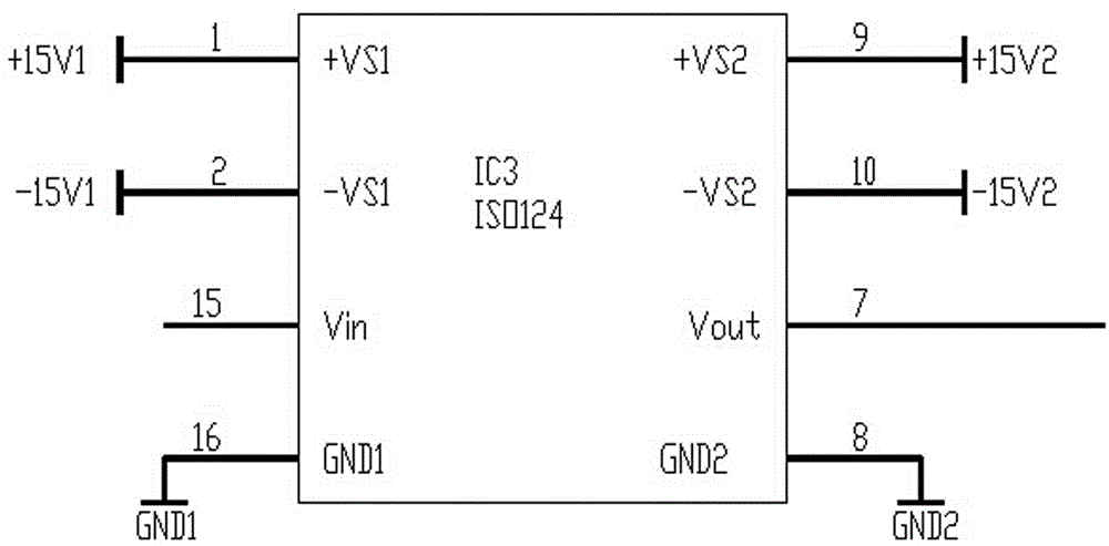
[0011] Specific implementation mode one: combine figure 1 This embodiment is described. This embodiment consists of a conversion amplifier 1 with a high common-mode rejection ratio, a voltage operation adjustment circuit 2, a voltage isolation module circuit 3, a second group of driving voltage generation circuits 4 for electronic throttles, a first group of isolated power supplies 5, The second group of isolated power supply 6 is composed;
[0012] The output signal of the mechanical throttle control system of the engine test bench is connected to the signal input terminal of the conversion amplifier 1 with a high common-mode rejection ratio, and the signal output terminal of the conversion amplifier 1 with a high common-mode rejection ratio is connected to the signal input terminal of the voltage operation adjustment circuit 2, The signal output terminal of the voltage operation adjustment circuit 2 is connected to the input terminal of the voltage isolation module circuit 3...
specific Embodiment approach 2
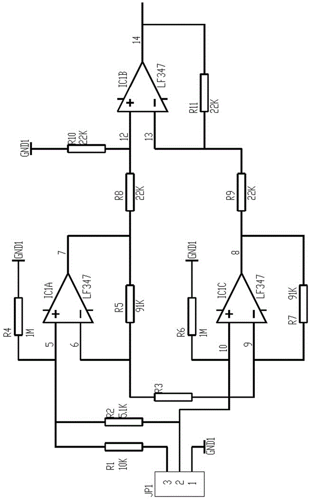
[0014] Specific implementation mode two: combination figure 2 Describe this embodiment, the difference between this embodiment and specific embodiment 1 is that the conversion amplifier 1 with high common mode rejection ratio is composed of resistors R1~R11, connector JP1, operational amplifier IC1A, operational amplifier IC1B, and operational amplifier IC1C;
[0015] Pin 1 of connector JP1 is grounded, pin 2 of connector JP1 is connected to one end of resistor R2, one end of resistor R6 is connected to the same input end of operational amplifier IC1C, pin 3 of connector JP1 is connected to one end of resistor R1, and the other end of resistor R1 One end is connected to the other end of the resistor R2, one end of the resistor R4 is connected to the same input end of the operational amplifier IC1A, the other end of the resistor R4 is grounded, and the reverse input end of the operational amplifier IC1A is connected to one end of the resistor R3 and one end of the resistor R5. ...
specific Embodiment approach 3
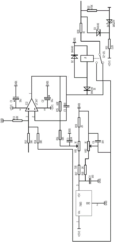
[0016] Specific implementation mode three: combination image 3 Describe this embodiment, the difference between this embodiment and specific embodiment 1 is that the voltage operation adjustment circuit 2 is composed of resistors R12~R22, operational amplifier IC2, electrolytic capacitor C1, electrolytic capacitor C2, capacitors C3~C6, adjustable resistor Composed of VR1, adjustable resistor VR2, three-terminal voltage regulator integrated circuit 7805, diodes D1~D3, voltage regulator diode D4, and relay J1;
[0017] One end of the resistor R12 is the input terminal of the input signal and connected to the output terminal of the operational amplifier IC1B of the conversion amplifier 1 with a high common mode rejection ratio, and the other end of the resistor R12 is in the same direction as the one end of the resistor R13, one end of the resistor R14 and the operational amplifier IC2 The input terminal is connected, the other end of the resistor R13 is grounded, the positive t...
PUM
 Abstract
Description
Claims
Application Information
 - R&D
- Intellectual Property
- Life Sciences
- Materials
- Tech Scout
- Unparalleled Data Quality
- Higher Quality Content
- 60% Fewer Hallucinations
Browse by: Latest US Patents, China's latest patents, Technical Efficacy Thesaurus, Application Domain, Technology Topic, Popular Technical Reports.
© 2025 PatSnap. All rights reserved.Legal|Privacy policy|Modern Slavery Act Transparency Statement|Sitemap|About US| Contact US: help@patsnap.com


