Two-dimensional short-range microwave holographic imaging method

A holographic imaging and short-range technology, applied in radio wave measurement systems, radio wave reflection/re-radiation, utilization of re-radiation, etc., can solve problems such as low resolution, improve efficiency, reduce implementation costs, and eliminate confusion The effect of stacking

Inactive Publication Date: 2015-03-25
GUILIN UNIV OF ELECTRONIC TECH +1
View PDF2 Cites 3 Cited by
  • Summary
  • Abstract
  • Description
  • Claims
  • Application Information

AI Technical Summary

Problems solved by technology

[0003] The technical problem to be solved by the present invention is the deficiency of low resolution existing in the existing short-range microwave holographic imaging method, and a two-dimensional short-range microwave holographic imaging method is provided

Method used


Image

  • Two-dimensional short-range microwave holographic imaging method
  • Two-dimensional short-range microwave holographic imaging method
  • Two-dimensional short-range microwave holographic imaging method

Examples


Embodiment Construction

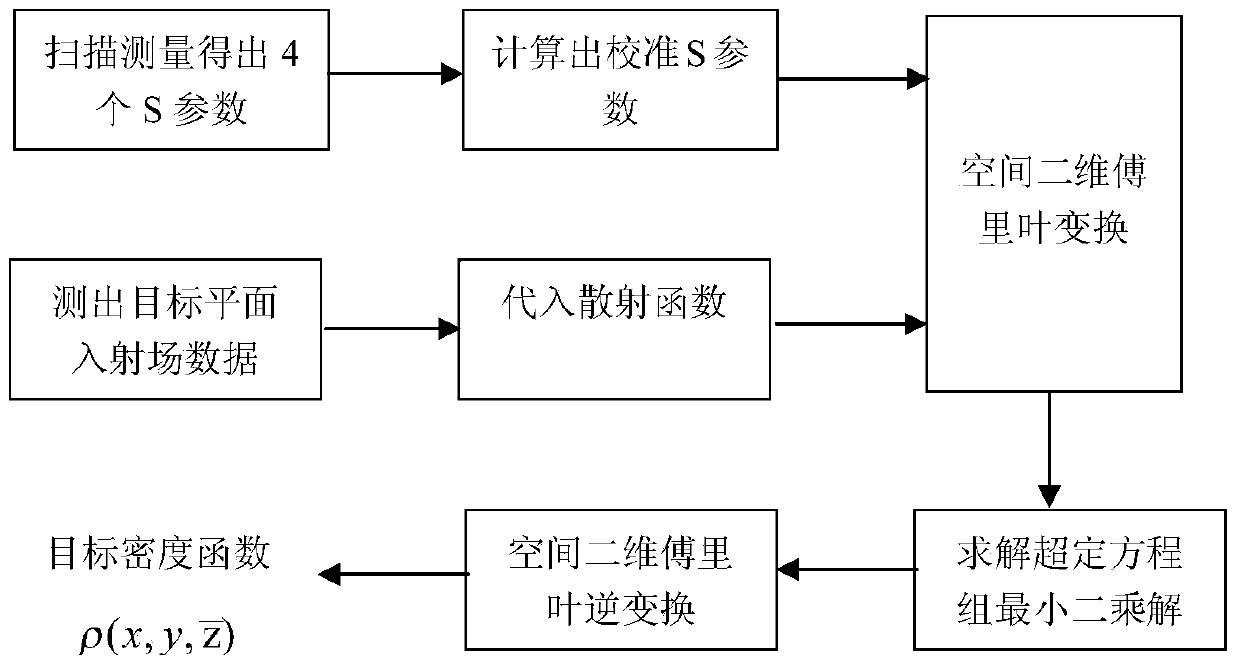
[0030] A two-dimensional short-range microwave holographic imaging method, such as figure 1 As shown, it specifically includes the following steps:

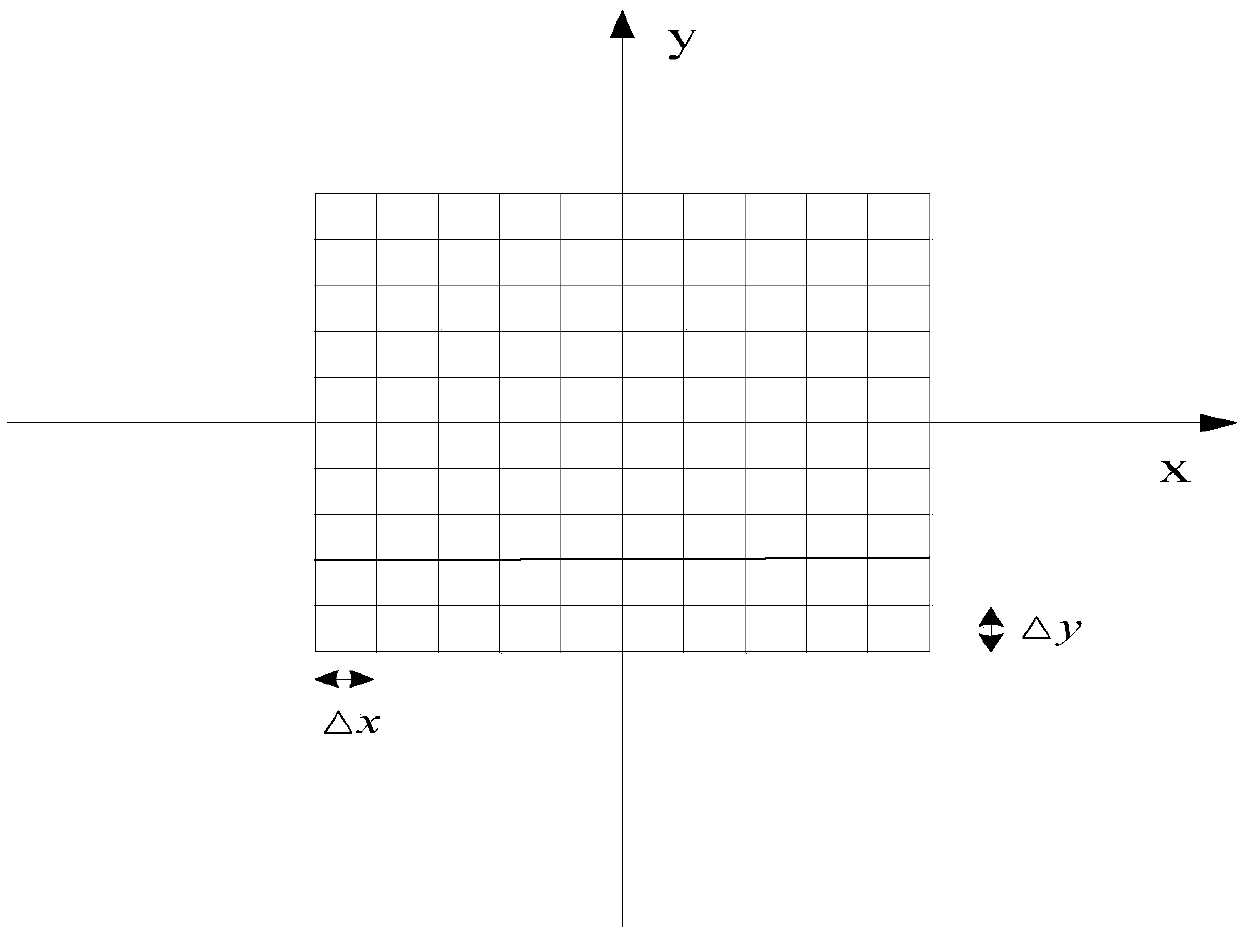
[0031] Step 1, set the start and end positions and scanning paths of the X-axis and Y-axis of the transmitting antenna and the receiving antenna respectively. Both the transmitting antenna and the receiving antenna are half-wave dipole antennas or horn antennas.

[0032] Step 2. Place the target to be reconstructed between the transmitting antenna and the receiving antenna. The transmitting antenna, the receiving antenna and the target form a two-port network, in which the transmitting antenna and the receiving antenna are used as two ports.

[0033] Step 3, according to the settings in step 1, the transmitting antenna and the receiving antenna are controlled to scan the target to be reconstructed, thereby obtaining 4 S parameters at each scanning position. The four S parameters of each scanning position are obtained by using t...


PUM


Abstract

The invention discloses a two-dimensional short-range microwave holographic imaging method. According to the method, parameter data of an objective scattered field and parameter data of an objective incident field are obtained through actual measuring or a simulation mode, the more real objective scattered field and the more real objective incident field can be obtained, and the irrationality that an incident field is assumed as spherical waves or cylindrical waves in the short-range millimeter wave holographic imaging technology is overcome; the least square solution of an overdetermined equation utilized in an objective image is solved and serves as two-dimensional Fourier transform of an objective function, the range of the imaging objective can be enlarged, and the imaging definition and the accuracy of an objective at different background environments can be improved.

Description

technical field [0001] The invention belongs to the field of microwave holographic imaging, and in particular relates to a two-dimensional short-range microwave holographic imaging method. Background technique [0002] Microwave holography is a fast inversion technology. It is extended from the traditional optical holography technology. It mainly relies on measuring the amplitude and phase of the target scattering field to obtain the target hologram, and then obtains the target microwave image through inversion. At present, the microwave holographic imaging method is mainly the short-range millimeter-wave holographic imaging method. In this method, spherical waves or cylindrical waves are used to replace the incident field, and the backscattering data of the target are collected through the transmitting and receiving antennas set on the same side of the target. ; Then directly perform two-dimensional Fourier transform on these scattering data, and then multiply a phase compe...

Claims


Application Information

Patent Timeline
Patent Type & Authority Applications(China)
IPC IPC(8): G01S13/89
CPCG01S13/89
Inventor 王俊义劳保强龚赟符杰林李燕龙刘争红郑霖仇洪冰王玫林基明安涛
Owner GUILIN UNIV OF ELECTRONIC TECH
Why Eureka
Try Eureka