Transflective liquid crystal display panel and liquid crystal display

A liquid crystal panel, transflective technology, applied in the field of liquid crystal display, can solve the problems of complex manufacturing process of liquid crystal panel, large color difference between transmission area and reflection area, difficult control of cell thickness uniformity, etc., to achieve improved display quality, vertical electric field Uniform and lower driving voltage effect

Inactive Publication Date: 2015-03-25
TCL CHINA STAR OPTOELECTRONICS TECH CO LTD
View PDF6 Cites 4 Cited by
  • Summary
  • Abstract
  • Description
  • Claims
  • Application Information

AI Technical Summary

Problems solved by technology

[0005] However, the disadvantage of the transflective liquid crystal panel is that the light emitted from the transmissive area only passes through the liquid crystal layer once, while the light emitted from the reflective area passes through the liquid crystal layer twice, thus causing different light sources in the transflective liquid crystal display. The emitted light has a different optical path (optical path) in the reflective area and the transmissive area, which makes the color difference between the transmissive area and the reflective area larger, resulting in color incongruity in the image displayed in the transflective liquid crystal display.
However, due to the difference in cell thickness of the liquid crystal cell in the transflective liquid crystal panel of this structure, the manufacturing process of the liquid crystal panel is complicated, and the uniformity of the cell thickness is not easy to control.

Method used


Image

  • Transflective liquid crystal display panel and liquid crystal display
  • Transflective liquid crystal display panel and liquid crystal display
  • Transflective liquid crystal display panel and liquid crystal display

Examples


Embodiment Construction

[0020] In order to enable those skilled in the art to better understand the technical solutions of the present invention, the transflective liquid crystal panel and the liquid crystal display of the present invention will be described in further detail below with reference to the accompanying drawings and specific embodiments.

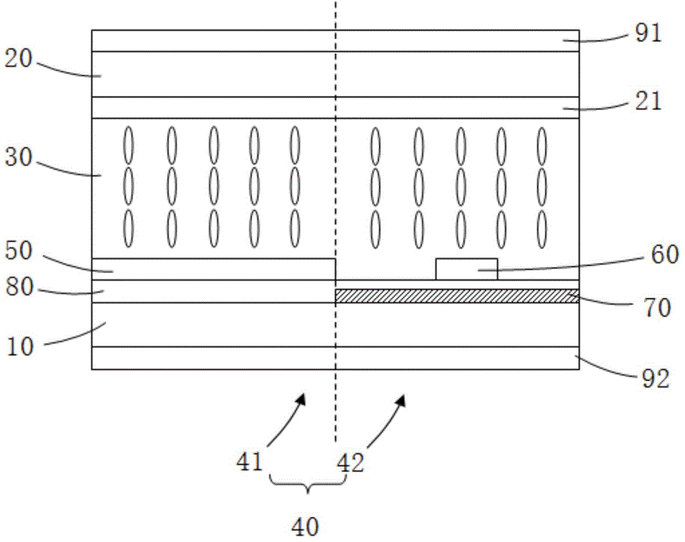
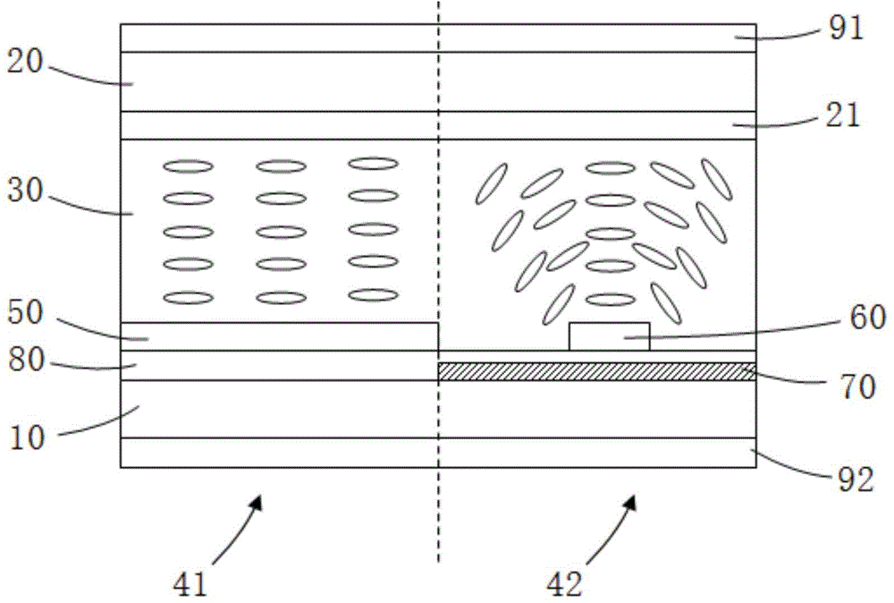
[0021] Refer to figure 1 with figure 2 ,among them figure 1 It is a schematic diagram of the structure of the transflective liquid crystal panel provided by this embodiment when no voltage is applied. figure 2 It is a schematic diagram of the structure of the transflective liquid crystal panel provided by this embodiment when a voltage is applied. The transflective liquid crystal panel includes an array substrate 10 and a color filter substrate 20 arranged oppositely, and a liquid crystal layer 30 located between the array substrate 10 and the color filter substrate 20. The array substrate 10 includes a plurality of pixel regions 40, Each of the pixel ar...


PUM


Abstract

The invention discloses a transflective liquid crystal display panel. The transflective liquid crystal display panel comprises an array substrate, a color film substrate and a liquid crystal layer between the array substrate and the color film substrate, and the array substrate and the color film substrate are in opposite arrangement. The array substrate comprises a plurality of pixel regions, each pixel region comprises a transmission area and a reflection area, and the color film substrate is provided with a common electrode layer positioned on one side, close to the liquid crystal layer, of the color film substrate. On the array substrate, first pixel electrodes are arranged in the transmission areas to enable the liquid crystal display panel in the transmission areas to form an electrode structure in a VA (vertical alignment) mode, and second pixel electrodes are arranged in the reflection areas to enable the liquid crystal display panel in the reflection areas to form an electrode structure in an ASV (action script viewer) mode. The invention further discloses a liquid crystal display with the transflective liquid crystal display panel.

Description

Technical field [0001] The invention belongs to the technical field of liquid crystal display, and relates to a transflective liquid crystal panel and a liquid crystal display including the liquid crystal panel. Background technique [0002] At present, the liquid crystal display (Liquid Crystal Display: LCD for short) has become a mainstream product in the market with its excellent performance and mature technology. The liquid crystal panel is a key component in the liquid crystal display. The liquid crystal panel is mainly formed by the color filter substrate and the array substrate, and the liquid crystal is filled between the color filter substrate and the array substrate to form a liquid crystal cell. Liquid crystal panels can be classified into transmissive, reflective, and transflective according to the type of light source. [0003] Among them, the transmissive liquid crystal panel mainly uses the backlight as the light source, and the backlight is provided behind the liqu...

Claims


Application Information

Patent Timeline
Patent Type & Authority Applications(China)
IPC IPC(8): G02F1/1343G02F1/1335G02F1/1333
CPCG02F1/133345G02F1/133553G02F1/1343G02F1/133555G02F1/133707G02F1/1393G02F1/133514G02F1/133528G02F1/134309G02F2201/121G02F2201/123
Inventor 谢畅
Owner TCL CHINA STAR OPTOELECTRONICS TECH CO LTD
Why Eureka
Try Eureka