Light emitting device and projection device

A light-emitting device and filter device technology, applied in projection devices, optics, instruments, etc., can solve the problems of large volume, complex structure of laser light source, and insufficient compact system design, and achieve the effect of simplifying heat dissipation design and reducing system volume

Inactive Publication Date: 2015-03-25
杨毅
View PDF7 Cites 5 Cited by
  • Summary
  • Abstract
  • Description
  • Claims
  • Application Information

AI Technical Summary

Problems solved by technology

However, at present, the laser light source has a complex structure and a large volume, and there is a problem that the system design is not compact enough in the application

Method used


Image

  • Light emitting device and projection device
  • Light emitting device and projection device
  • Light emitting device and projection device

Examples


Embodiment Construction

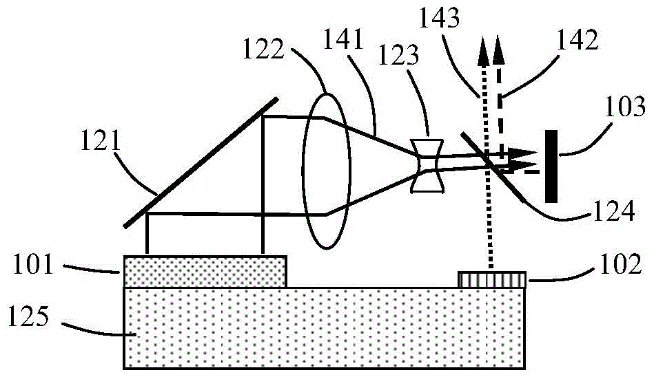
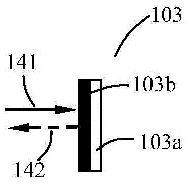
[0013] The present invention proposes a light-emitting device, the structural schematic diagram of the first embodiment is as follows Figure 1A shown. The light-emitting device includes a laser light source 101 for emitting a laser beam (taking light 141 as an example); includes a reflection device 121 placed on the light-emitting direction of the laser light source 101, and also includes a spectroscopic filter device 124 and a wavelength conversion device 103, and the laser beam 141 is deflected by 90 degrees after being reflected by the reflection device 121, and then transmits the spectral filter device 124 and is incident on the wavelength conversion device 103. The first outgoing light 142 is formed by being reflected by the spectroscopic filter device 124 ; wherein, the spectroscopic action surface of the spectroscopic filter device 124 is perpendicular to the reflective action surface of the reflective device 121 .

[0014] The light emitting device also includes a lig...


PUM


Abstract

The invention provides a light emitting device and a protection device. The light emitting device comprises a laser source and a reflection device arranged in the light emitting direction of the laser source, and further comprises a light splitting and filtering device and a wavelength conversion device. Laser beams are reflected by the reflection device and then deflect by 90 degrees and then are transmitted to the light splitting and filtering device to come into the wavelength conversion device, the wavelength conversion device absorbs laser and emits excited light to the light splitting and filtering device, and the excited light is reflected by the light splitting and filtering device to form first emergent light. The light emitting device further comprises a light emitting diode light source, and light emitted by light emitting diode light source to the light splitting and filtering device is transmitted to the light splitting and filtering device to form second emergent light. The light emitting device further comprises a cooling backboard, and the bottom face of the light emitting diode light source and the bottom face of the laser source are fixed to the cooling faces of the cooling backboard. The first emergent light is emitted in the direction opposite to the laser source, the light emitting diode light source and the laser source can share the same cooling backboard, and accordingly cooling design is greatly simplified.

Description

technical field [0001] The invention relates to the field of display technology, in particular to a light emitting device and a projection device using the light emitting device. Background technique [0002] Projection technology has been widely used in our life and work, such as projectors. At present, the light source in projection technology is still dominated by high-pressure mercury lamps. However, the lifespan of the high-pressure mercury lamp is only a few thousand hours. If the lamp is used for a long time, it will dim and affect the display effect. Alternatives to high-pressure mercury lamps include LED light sources and laser light sources, both of which have the advantage of long life, but the difference is that LED light sources are not bright enough but cheap, and laser light sources are bright but expensive. [0003] From the perspective of technological development, it is an inevitable trend for laser light sources to replace high-pressure mercury lamps. ...

Claims


Application Information

Patent Timeline
Patent Type & Authority Applications(China)
IPC IPC(8): G03B21/20G03B21/16
CPCG03B21/2033G03B21/16
Inventor 杨毅
Owner 杨毅
Why Eureka
Try Eureka