IGBT-based high-power pulse type constant-current load circuit

A load circuit, pulse-type technology, applied in the direction of measuring electricity, measuring electrical variables, components of electrical measuring instruments, etc., can solve the problems of difficult control and maintenance, low parallel withstand voltage of low-power transistors, etc., and achieves simple and easy heat dissipation design. The effect of large heat dissipation area and high power handling capacity

Pending Publication Date: 2022-05-06
杭州布雷科电气有限公司 +1
View PDF0 Cites 1 Cited by
  • Summary
  • Abstract
  • Description
  • Claims
  • Application Information

AI Technical Summary

Problems solved by technology

[0005] In this application, the IGBT is used as the electronic load. The IGBT has a high power handling capability, and has the advantages of high input impedance of the MOSFET and low conduction voltage drop of the GTR. A single IGBT can handle large power without Multi-channel parallel connection is required, simple and reliable, large heat dissipation area, simple and easy heat dissipation design, and solves the problems of small power transistors connected in parallel with low withstand voltage and difficult control and maintenance

Method used


Image

  • IGBT-based high-power pulse type constant-current load circuit
  • IGBT-based high-power pulse type constant-current load circuit
  • IGBT-based high-power pulse type constant-current load circuit

Examples


Embodiment Construction

[0033] Exemplary embodiments of the present disclosure will be described in more detail below with reference to the accompanying drawings. Although exemplary embodiments of the present disclosure are shown in the drawings, it should be understood that the present disclosure may be embodied in various forms and should not be limited by the embodiments set forth herein. Rather, these embodiments are provided for more thorough understanding of the present disclosure and to fully convey the scope of the present disclosure to those skilled in the art.

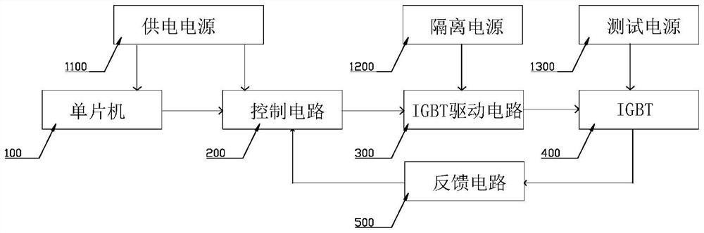
[0034] High-power pulse type constant current load circuit based on IGBT, such as figure 1 As shown, it includes: a single chip microcomputer 100 , a control circuit 200 , an IGBT drive circuit 300 , an IGBT 400 and a feedback circuit 500 connected in sequence. The single-chip microcomputer 100 receives the externally set current pulse parameters, outputs a control signal to the control circuit 200, the control circuit 200 outputs ...


PUM


Abstract

The invention provides a high-power pulse type constant-current load circuit based on an IGBT. The high-power pulse type constant-current load circuit comprises a single-chip microcomputer, a control circuit, an IGBT driving circuit, an IGBT and a feedback circuit which are connected in sequence. The single chip microcomputer receives externally set current pulse parameters and outputs a control signal to the control circuit, the control circuit outputs a reference level after performing data processing on the control signal, and the feedback circuit samples a current pulse output by the IGBT and converts the current pulse into a feedback level to drive the IGBT driving circuit to work together with the reference level and control the IGBT to output the required current pulse; the gate electrode of the IGBT is connected with the IGBT driving circuit, the collector electrode of the IGBT is connected with the test power supply, and the emitter electrode of the IGBT is connected with the feedback circuit. According to the invention, the IGBT is used as an electronic load, and the problems of small parallel withstand voltage and difficult control and maintenance of small-power transistors are solved. Through the mutual cooperation of the control circuit, the IGBT driving circuit and the feedback circuit, the IGBT output current can be accurately adjusted, so that the output current pulse of the IBGT meets the design requirement.

Description

technical field [0001] The application relates to the field of electronic testing, in particular to a high-power pulse-type constant-current load circuit based on IGBT. Background technique [0002] With the development of new energy sources, the power of electronic loads is increasing, and the actual use parameter span is also increasing. Traditionally, low-power transistors (MOS devices) are used as loads to design constant-current load circuits. The application of constant-current load circuits is limited. The withstand voltage of a single low-power transistor is generally 100V, and the pulse power is generally around 100W, which is insufficient. The constant current solution using low-power transistors is suitable for low-power applications, and cannot test power supplies above 100V. When used under high-power conditions, on the one hand, the reliability cannot be well guaranteed. On the other hand, the high-voltage environment requires multiple MOSFETs to be connected ...

Claims


Application Information

Patent Timeline
Patent Type & Authority Applications(China)
IPC IPC(8): G01R1/28
CPCG01R1/28
Inventor 徐高东陈颖周虹
Owner 杭州布雷科电气有限公司
Why Eureka
Try Eureka