A two-phase cooling system based on r134a

A cooling system and condenser technology, applied in cooling/ventilation/heating transformation, etc., can solve the problems of poor insulation performance, limited cooling power, high noise, etc., and achieve the effects of excellent insulation performance, small flow rate and low energy consumption

Active Publication Date: 2018-07-10
上海俱瀚机械设备科技有限公司
View PDF5 Cites 1 Cited by
  • Summary
  • Abstract
  • Description
  • Claims
  • Application Information

AI Technical Summary

Problems solved by technology

[0002] High-power power electronic equipment uses semiconductor power devices such as IGBTs as electronic switches to rectify the AC power supply, invert the DC power supply, and change the characteristic parameters such as amplitude, frequency and phase angle during the conversion process, so as to complete the power supply for specific purposes. Control to meet the requirements of industrial use. The switching frequency of silicon semiconductor power devices ranges from hundreds of hertz to tens of thousands of hertz. The heat of these two parts constitutes the heat generation of the power device. The premise of the normal operation of the power device is that the temperature of the PN junction is maintained below a certain range (usually below 125 degrees Celsius), and the heat generated must be dissipated in time, otherwise it will cause Overheating; the traditional cooling method uses air cooling, but its cooling power is very limited, its environmental adaptability is poor, and its noise is large, making it unsuitable for high-power harsh environments and occasions with slightly higher environmental assessment indicators. Water-cooling systems are suitable for high-power harsh environments. Closed cooling function, but due to the poor insulation performance of water itself, the damage caused by water leakage is huge, so the reliability and safety are not high in high-voltage occasions. On the one hand, the use of antifreeze will reduce the cooling effect

Method used


Image

  • A two-phase cooling system based on r134a
  • A two-phase cooling system based on r134a
  • A two-phase cooling system based on r134a

Examples


Embodiment Construction

[0018] The present invention will be further described below in conjunction with accompanying drawing and specific embodiment:

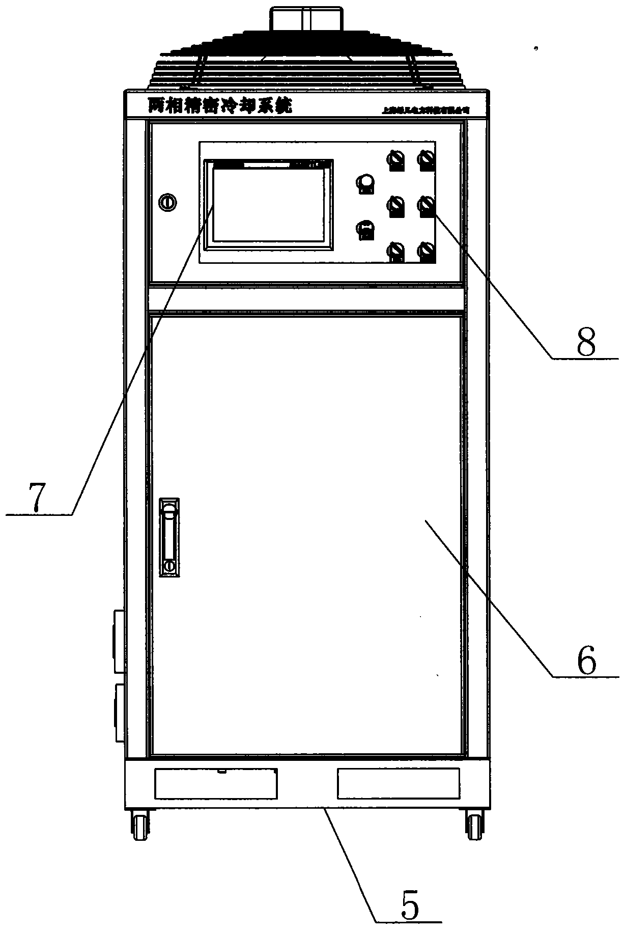
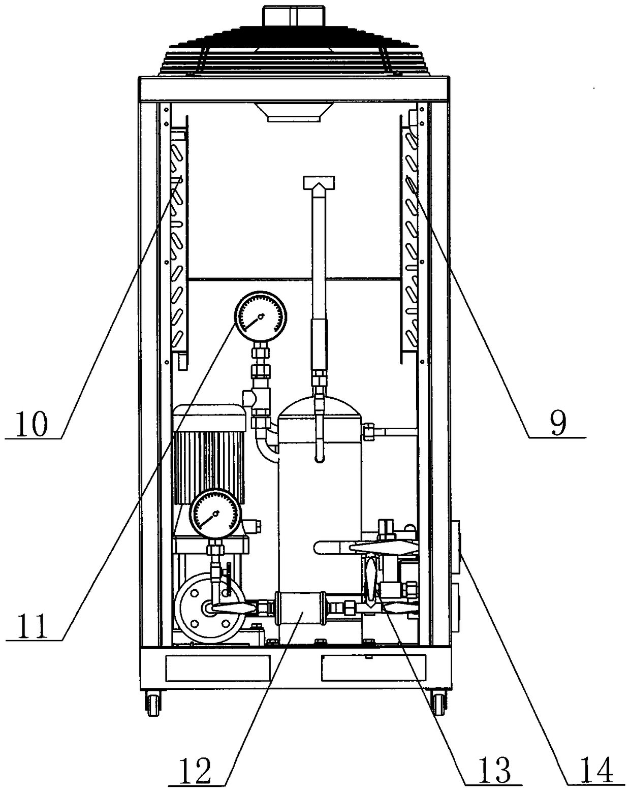
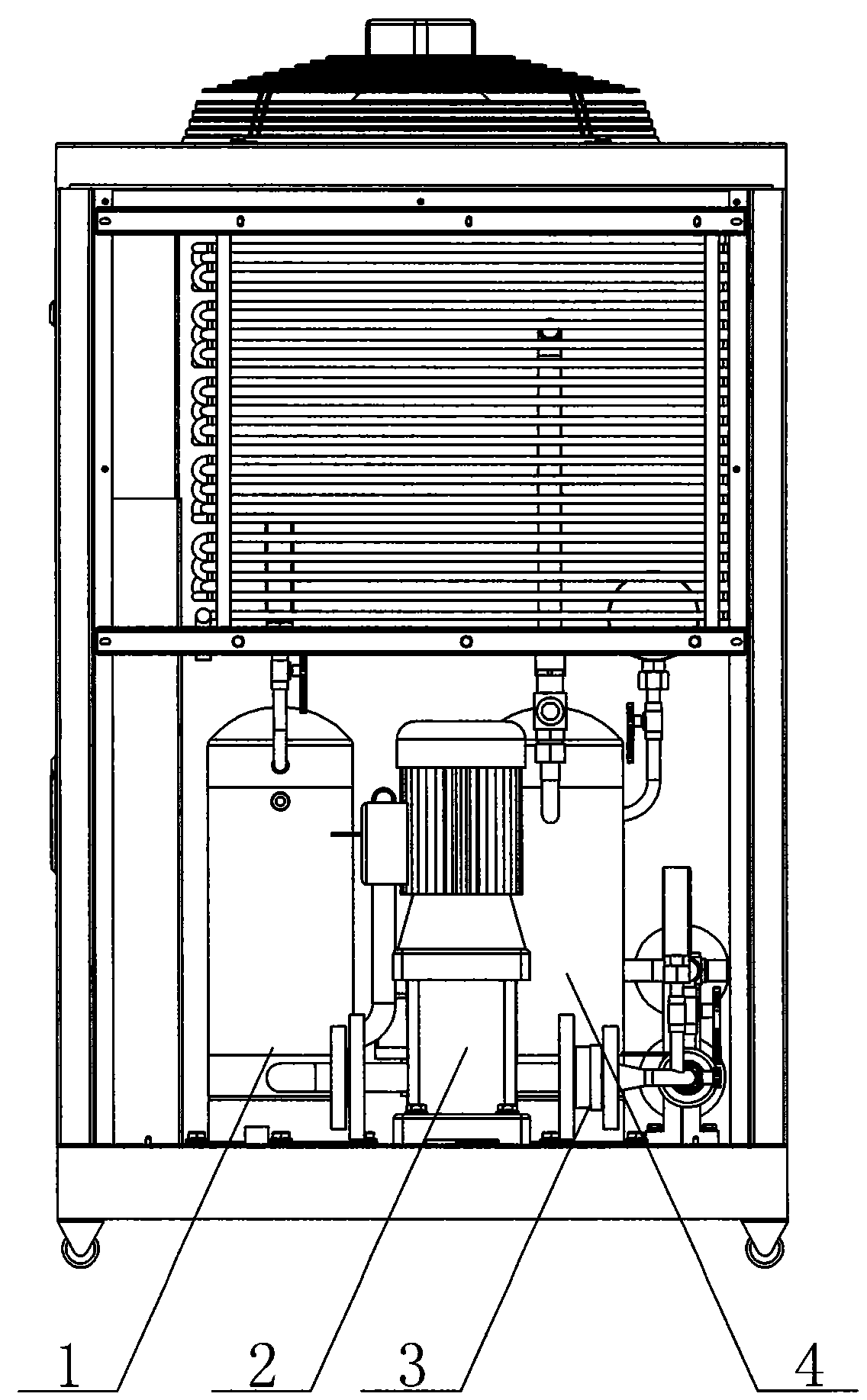
[0019] A two-phase cooling system based on R134a, such as figure 1 , 2 , 3, including: a cabinet body 5, a circulating pump 2 is arranged on the inner lower floor of the cabinet body 5, a control panel 6 is arranged on the front side of the cabinet body 5, an inlet and outlet flange 14 is installed on the left side of the cabinet body 5, and the inlet and outlet method The flange 14 includes an inlet flange and an outlet flange. The inlet and outlet flanges 14 are externally connected to the radiator of the power electronic equipment through a flexible connection tube. The radiator of the power electronics equipment is installed on the power electronics equipment. The middle layer of the cabinet body 5 is arranged with a condenser 9 The separation tank 4 and the liquid storage tank 1 are arranged on the inner lower floor of the cabinet 5, the separ...


PUM


Abstract

A two-phase cooling system based on R134a comprises a cabinet body. A circulating pump, an isolation tank and a liquid storage tank are arranged on a lower bottom plate inside the cabinet body. A condenser is arranged in the middle layer of the cabinet body. A control disc is arranged on the front side of the cabinet body. The left side of the cabinet body is equipped with an inlet-outlet flange comprising an inlet flange and an outlet flange. The inlet-outlet flange is externally connected with a power electronic device radiator through a soft connecting pipe, and the power electronic device radiator is mounted on a power electronic device. A sealed space formed by the circulating pump, the condenser, the isolation tank, the liquid storage tank and the soft connecting pipe is filled with an R134a medium with pressure. The system is advantaged in that the sealed cooling system has excellent insulation and cold-proof performance, and makes the power electronic device have excellent temperature uniformity.

Description

technical field [0001] The invention relates to a cooling system of power electronic equipment, in particular to a two-phase cooling system based on R134a. Background technique [0002] High-power power electronic equipment uses semiconductor power devices such as IGBTs as electronic switches to rectify the AC power supply, invert the DC power supply, and change the characteristic parameters such as amplitude, frequency and phase angle during the conversion process, so as to complete the power supply for specific purposes. Control to meet the requirements of industrial use. The switching frequency of silicon semiconductor power devices ranges from hundreds of hertz to tens of thousands of hertz. The heat of these two parts constitutes the heat generation of the power device. The premise of the normal operation of the power device is that the temperature of the PN junction is maintained below a certain range (usually below 125 degrees Celsius), and the heat generated must be ...

Claims


Application Information

Patent Timeline
Patent Type & Authority Patents(China)
IPC IPC(8): H05K7/20
Inventor 王学奎李磊
Owner 上海俱瀚机械设备科技有限公司
Why Eureka
Try Eureka