Self-tuning all-solid-state microwave source MPT, self-tuning device and control method
A control method and microwave source technology, applied in the field of chemical measurement, can solve the problems of unmatched system impedance, cumbersome operation, unfavorable instrument protection, etc., and achieve the effect of improving operability and service life, reducing experience requirements, and being beneficial to protection.
- Summary
- Abstract
- Description
- Claims
- Application Information
AI Technical Summary
Problems solved by technology
Method used
Image

Examples
Embodiment 1
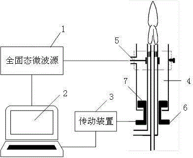
[0034] Such as figure 1 An all-solid-state microwave source MPT self-tuning device is shown, the microwave plasma torch (4) includes a coupling antenna (5) and an adjustment member (6), and it is characterized in that the device includes an all-solid-state microwave source (1) , control module (2), transmission device (3);
[0035] The all-solid-state microwave source is connected to the coupling antenna (5), the adjustment member (6) is connected to the transmission device (3), the transmission device (3) is connected to the control module (2), The control module (2) is connected to the all-solid-state microwave source;
[0036] Wherein, the all-solid-state microwave source generates a microwave electromagnetic field to provide microwave energy for the microwave plasma torch (4), and at the same time obtains feedback information of the microwave plasma torch (4) from the coupling antenna (5), and the all-solid-state microwave source converts the feedback information into Th...
Embodiment 2
[0046] Based on the all-solid-state microwave source MPT self-tuning device described in Embodiment 1, this embodiment provides a image 3 The MPT self-tuning control method of the all-solid-state microwave source shown. The MPT self-tuning control method of the all-solid-state microwave source described in this embodiment is a heuristic method.
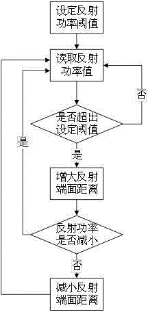
[0047] The all-solid-state microwave source MPT self-tuning control method is used in the above-mentioned self-tunable all-solid-state microwave source MPT. The self-tuning control method in the control module (2) includes the following steps:
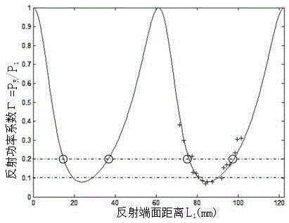
[0048] S1: Set the threshold of the reflection power coefficient;
[0049] S2: Read the real-time reflected power as the first reflected power value, and calculate the first reflected power coefficient for the real-time reflected power value;
[0050] S3: judging whether the first reflected power coefficient is greater than the threshold, if yes, then enter step S4, otherwise, return to st...
PUM
 Abstract
Description
Claims
Application Information
 - R&D
- Intellectual Property
- Life Sciences
- Materials
- Tech Scout
- Unparalleled Data Quality
- Higher Quality Content
- 60% Fewer Hallucinations
Browse by: Latest US Patents, China's latest patents, Technical Efficacy Thesaurus, Application Domain, Technology Topic, Popular Technical Reports.
© 2025 PatSnap. All rights reserved.Legal|Privacy policy|Modern Slavery Act Transparency Statement|Sitemap|About US| Contact US: help@patsnap.com