
LED lamp design verification method and LED lamp design verification method application to externally-hung lamp or headlamp

A LED lamp, design verification technology, applied in special data processing applications, calculations, instruments, etc.

Inactive Publication Date: 2015-03-25
FSL AUTOTECH
View PDF2 Cites 5 Cited by
  • Summary
  • Abstract
  • Description
  • Claims
  • Application Information

AI Technical Summary

Problems solved by technology

[0008] The purpose of the present invention is to provide a LED lamp design verification method and its application in external lights and headlights, aiming to solve the problem of how to adopt a more reasonable heat conduction arrangement and heat dissipation scheme in the case of harsh heat exchange conditions

Method used


Image

  • LED lamp design verification method and LED lamp design verification method application to externally-hung lamp or headlamp
  • LED lamp design verification method and LED lamp design verification method application to externally-hung lamp or headlamp
  • LED lamp design verification method and LED lamp design verification method application to externally-hung lamp or headlamp

Examples


Embodiment 1

[0070] Example 1 Design and Numerical Simulation Verification of External LED Car Retrofit Lamp

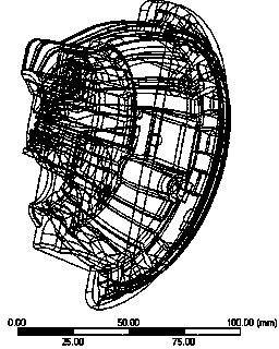
[0071] Step S1: Determine the structure of the LED lamp: such as Figure 2-4 Shown is the structural diagram of the plug-in LED car modified lamp designed and determined by CAD software, the imitation lumen lamp bead on the middle substrate of the lamp, and the COB package (chip On board) lamp bead at the bottom of the lamp;

[0072]Modeling of LED lamps and LED lamp beads: 1. The high-power imitation lumen lamp beads are welded on the aluminum-based printed circuit board (Metal Core Printed Circuit Board, MCPCB) inside the car lamp, and are located in the external LED car modification lamp. The middle part has a heating power of 7W and is packaged in a heat-sinking SMT (Surface Mount Technology). The structure of the lamp bead is as follows: Figure 5 As shown, the material layers, thickness and thermal conductivity of the lamp bead are shown in Table 1; 2. The COB package high-...

Embodiment 2

[0092] Embodiment 2 is to the design and numerical simulation verification of replaceable LED headlights

[0093] Step S1: Determine the structure of the LED lamp, and model the LED lamp and LED lamp beads: such as Figure 7-9 As shown, the replaceable LED headlights with vertically arranged fins, the replaceable LED headlights with horizontally arranged fins, and the arrangement of lamp beads on the replaceable lamp substrate are designed and determined by CAD software. Structural diagram; the replaceable LED headlight adopts a 1.6mm*1.6mm high-power lamp bead array, and the thermal resistance of each lamp bead is about 0.4C / W.


PUM

PropertyMeasurementUnit
Heating poweraaaaaaaaaa

Abstract

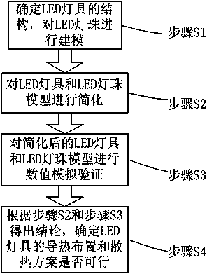
The invention discloses an LED lamp design verification method and LED lamp design verification method application to an externally-hung lamp or a headlamp. The design verification method includes the following steps that the structure of an LED lamp is determined, and the LED lamp and LED lamp beads are modeled; an LED lamp model and an LED lamp bead model are simplified; numerical simulation verification is performed on the simplified LED lamp model and the simplified LED lamp bead model; a conclusion is drawn, and whether heat-conduction arrangement and a heat-dissipation scheme of the LED lamp are practicable or not is determined. The conclusion is drawn through structure determination, modeling and numerical simulation solution, the LED lamp is structurally designed before being put into production, and the reasonable heat-conduction arrangement and the heat-dissipation scheme are obtained through performing simulation verification on heat and heat-dissipation requirements of all parts of the lamp in the working process; due to the efficient heat-dissipation design, the heat generated by a chip is conducted, effective exchange between the heat and the environment is performed, the heat of the LED lamp is reasonably dissipated when the LED lamp works, the LED chip works at a safe temperature, the lighting effect and reliability of the LED chip are improved, and the service life of the LED chip is prolonged.

Description

technical field [0001] The invention relates to a design and simulation verification method, in particular to a design verification method of an LED lamp and its application in external hanging lamps and headlights. Background technique [0002] As a new type of lighting source technology, LED has many advantages such as high light efficiency, long life, small size, and fast response. Due to the limitation of the power used, the early LEDs were mainly used in instrument display, household lighting and other fields, and after being introduced into the field of automotive lighting, they were only used as taillights or auxiliary lighting. [0003] The main bottleneck of LEDs used in automotive headlights is heat dissipation. Since the light conversion efficiency of LEDs is only 20-30%, a large part of the energy will be converted into heat, which will increase the temperature of the LED chip. The light efficiency, life and reliability of LED chips are greatly dependent on the ...

Claims


Application Information

Patent Timeline
IPC IPC(8): G06F17/50
Inventor 何孝文曾明虎张力张克强张任
Owner FSL AUTOTECH
Learn More