
Grid grading method for near-surface ground motion simulation

A classification method and ground motion technology, applied in the fields of engineering wave theory and seismology, which can solve problems such as high requirements on grid shape and discreteness

Inactive Publication Date: 2015-03-25
SHENYANG POLYTECHNIC UNIV
View PDF0 Cites 6 Cited by
  • Summary
  • Abstract
  • Description
  • Claims
  • Application Information

AI Technical Summary

Problems solved by technology

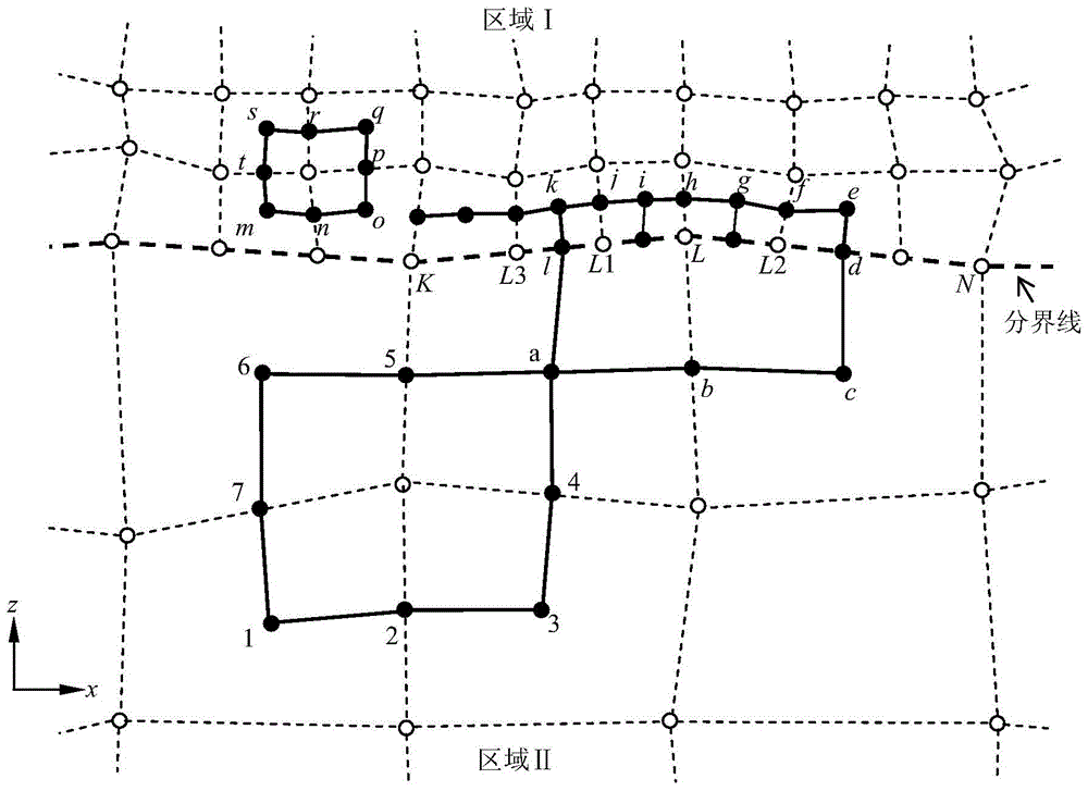
All of the above works have saved computational costs to varying degrees, but they have high requirements for the grid shape, that is, a rectangular grid is required to discretize the calculation area, which has limitations in dealing with undulating surfaces or internal irregular geometric boundaries.

Method used


Image

  • Grid grading method for near-surface ground motion simulation
  • Grid grading method for near-surface ground motion simulation
  • Grid grading method for near-surface ground motion simulation

Examples


Embodiment 1

[0159] Example 1: Comparison with Lamb analytical solution results

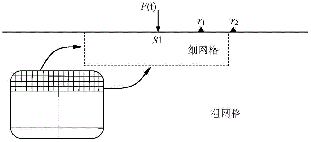
[0160] image 3 It is the computational model compared with the Lamb analytical solution. In the figure, the force source F(t)=exp[-α(t-t 0 )], α=90 and t 0 = 0.3s. The smaller area of ​​the calculation model is discretized with a 10m square grid, and the larger areas are discretized with a 30m, 50m, 70m and 90m square grid respectively. Two observation points r 1 and r 2 The distance from the loading point S1 is 2000m and 5310m respectively, and the observation point r 1 On a fine mesh surface, the observation point r 2 Located on the surface of the coarse grid and separated from the boundary line of the coarse and fine grid ( image 3 The dotted line in ) is 360m apart. The P wave velocity of the medium in the elastic half space is 5196m / s, the SV wave velocity is 3000m / s, and the density is 2300Kg / m 3 . The time step used in the calculation is 0.001s, and the calculation time is 4s.

[0161] ...

Embodiment 2

[0164] Example 2: Simulation of near-surface ground motion under complex site conditions

[0165] Figure 7 Computational models for sedimentary basins and undulating surfaces. In the figure, the observation point Ra is located at the apex of the left mountain peak, and the relative horizontal and vertical distances between the observation point Rc (located on the left edge of the basin) and Ra are 2.4km and 1.2km respectively; the observation point Rb is located at the apex of the right mountain peak , the relative horizontal and vertical distances between observation point Rd (located on the right edge of the basin) and Rb are 1.9km and 0.8km, respectively. Located on the mountainside on the left, a total of 19 observation points are set between observation points Ra and Rc; on the surface of the sedimentary basin, a total of 28 observation points are set between observation points Rc and Rd; on the right mountainside, observation point Rd A total of 12 observation points ...


PUM


Abstract

The invention relates to a grid grading method for near-surface ground motion simulation, and belongs to the field of engineering wave theory and seismology. The method comprises the following steps: firstly, a block to be researched is established, and a dynamic balance equation of the block to be researchedis established; secondly, the stress and displacement on the contour of the block to be researched are calculated; finally, by a recursive method, the stress field, displacement field and accelerated speed field of the block to be researched at the connecting part of a thick grid and a thin grid are calculated from time t to time t + <delta>t, and a speed field is calculated from time t - <delta>t / 2 to time t + <delta> t / 2. According to the method, an irregular grid with different steps can be adopted to disperse a calculation model, and the simulation process is efficient and flexible, and the calculation efficiency can be improved greatly.

Description

technical field [0001] The invention belongs to the fields of engineering wave theory and seismology, and mainly relates to the numerical simulation of ground motion near the surface, especially for the geological situation where the shear wave velocity difference between the surface soil layer and the bedrock is relatively large. Background technique [0002] In the depth range of tens of meters to several thousand meters below the surface, there are usually multiple low-velocity soil (rock) layers. Studies have shown that the low-velocity soil layer near the surface will greatly affect the amplitude and frequency spectrum characteristics of ground motion. Most of the near-surface is soil (rock) layer with low shear wave velocity. Numerical simulation technology requires that the allowable maximum spatial step size of the discrete grid meets the dispersion characteristics of the numerical method. That is, for seismic waves of the same frequency, the lower the shear wave vel...

Claims


Application Information

Patent Timeline
IPC IPC(8): G06F19/00
Inventor 栾宇鲍文博黄志强金生吉
Owner SHENYANG POLYTECHNIC UNIV
Learn More