Direct-current generator

A technology of DC generators and housings, which is applied in the direction of electrical components, electromechanical devices, and electric components, and can solve problems such as large voltage ripples of three-phase DC generators, unfavorable products widely used, and increased production costs of products, and achieve voltage The effects of small ripple, high reliability, and easy installation and connection

Inactive Publication Date: 2015-03-25
SOMER LEROY ELECTRO TECH FUZHOU CO LTD
View PDF3 Cites 1 Cited by
  • Summary
  • Abstract
  • Description
  • Claims
  • Application Information

AI Technical Summary

Problems solved by technology

However, the rectifier bridge of ordinary generators is usually installed inside the generator, and the rectifier bridge is usually connected in parallel with scattered diodes, so that the internal wiring arrangement is dense and the reliability of the generator is poor. Once the rectifier bridge inside the generator fails , it is necessary to dismantle the superimposed device first, and then perform maintenance, so it is not suitable for installation and maintenance
Moreover, the voltage ripple of this type of three-phase DC generator is relatively large, so the electrical performance of the generated voltage is also poor, so it is necessary to add a smoothing device such as a reactor to improve the electrical performance of the generated voltage
This will increase the production cost of the product as a whole, which is not conducive to the widespread use of the product.

Method used


Image

  • Direct-current generator
  • Direct-current generator
  • Direct-current generator

Examples


Embodiment Construction

[0024] The following description of preferred embodiments is exemplary only and in no way restricts the invention and its application or usage. The same reference numerals are used to denote the same components in the respective drawings, and thus the configurations of the same components will not be described repeatedly.

[0025] The technical solutions of the present invention will be further described below in conjunction with the accompanying drawings and specific embodiments.

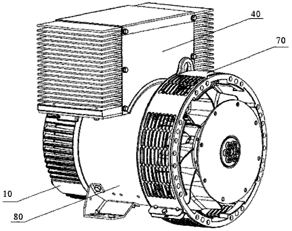
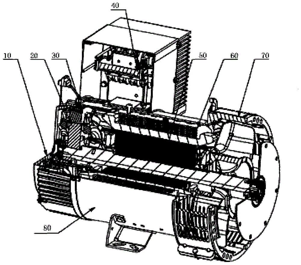
[0026] Figure 1-3 A direct current generator provided by the present invention is shown. as the picture shows, figure 1 It is a perspective view of a direct current generator of one of the embodiments of the present invention, figure 2 For such figure 1 The partial cross-sectional perspective view of the DC generator shown, wherein the DC generator includes a first end cover assembly 10, a second end cover assembly 70, a casing assembly 80, a main rotor 50, a main stator 60, a terminal assemb...


PUM


Abstract

The invention provides a direct-current generator. The direct-current generator comprises a first end cover component, a second end cover component, a machine shell component, a main stator, a main rotor, an exciter and a terminal component, wherein the first end cover component and the second end cover component are fixedly connected to the two ends of the machine shell component respectively, the main stator is fixedly arranged inside the machine shell component and is coaxial with the machine shell component, the main rotor is fixedly arranged on a rotary shaft coaxial with the machine shell component, located inside the main stator and coaxial with the main stator, the exciter is fixedly arranged inside the first end cover component and is coaxial with the machine shell component, and the terminal component is located outside the machine shell component. According to the direct-current generator, wiring is easy, installation and maintenance are easy, voltage rippers are small, and electrical performance is high.

Description

technical field [0001] The present invention relates to a DC generator, in particular to a low-voltage DC generator. Background technique [0002] With the continuous development of power electronics, micro-electric technology and other related fields, generators have experienced the development process from DC to AC, from brush to brushless. [0003] In the prior art, low-voltage DC generators are roughly divided into two categories. One is low-voltage DC permanent magnet machines. This type of DC generator uses high-performance permanent magnet steel as the excitation material, which is expensive and not suitable for promotion. The other type is an ordinary three-phase low-voltage DC generator, which adopts a conventional three-phase design and is widely used. However, the rectifier bridge of ordinary generators is usually installed inside the generator, and the rectifier bridge is usually connected in parallel with scattered diodes, so that the internal wiring arrangemen...

Claims


Application Information

Patent Timeline
Patent Type & Authority Applications(China)
IPC IPC(8): H02K11/00H05K7/20H02K11/049H02K11/33
Inventor 陈艺山连文津方子亮阙善材王杏
Owner SOMER LEROY ELECTRO TECH FUZHOU CO LTD
Why Eureka
Try Eureka