Insecticidal device

A technology of an insecticidal device and a fixing device, applied in the field of agriculture and forestry, can solve the problems of short service life, high use cost, increase use cost, etc., and achieve the effects of good technical and economic value, low manufacturing cost and long service life.

Inactive Publication Date: 2015-04-01
CHONGQING LIZHENYUAN AGRI & FORESTRY TECH
View PDF12 Cites 1 Cited by
  • Summary
  • Abstract
  • Description
  • Claims
  • Application Information

AI Technical Summary

Problems solved by technology

[0003] Existing bug-inducing lamps use conventional LED or black light tubes. Although black light tubes are cheap, their service life is short and the cost of use in the entire life cycle is high. Frequent replacement of black light tubes is also very troublesome; although LED lights use Long life, but expensive
Moreover, the common disadvantage of these two lights is that they need electricity, which not only requires energy consumption, but also leads to high use costs, and it is also a headache to solve the power supply in remote mountainous areas.
[0004] In addition, because the existing pest-killing lamp kills pests through the high-voltage grid, it brings the following defects: 1. The high-voltage grid always maintains a high-voltage state to bring certain safety hazards, and electric shock accidents are prone to occur. ; 2, power consumption is needed, which will not only increase the cost of use, but also solve the problem of power supply in remote mountainous areas; It will reduce the insecticidal effect of the insecticidal lamp; 4. For some larger pests, the existing high-voltage electric grid often only stuns them, but does not kill them, so that the insecticidal effect cannot be achieved. Purpose

Method used


Image

  • Insecticidal device
  • Insecticidal device
  • Insecticidal device

Examples


Embodiment Construction

[0025] Below in conjunction with accompanying drawing and embodiment the present invention will be further described:

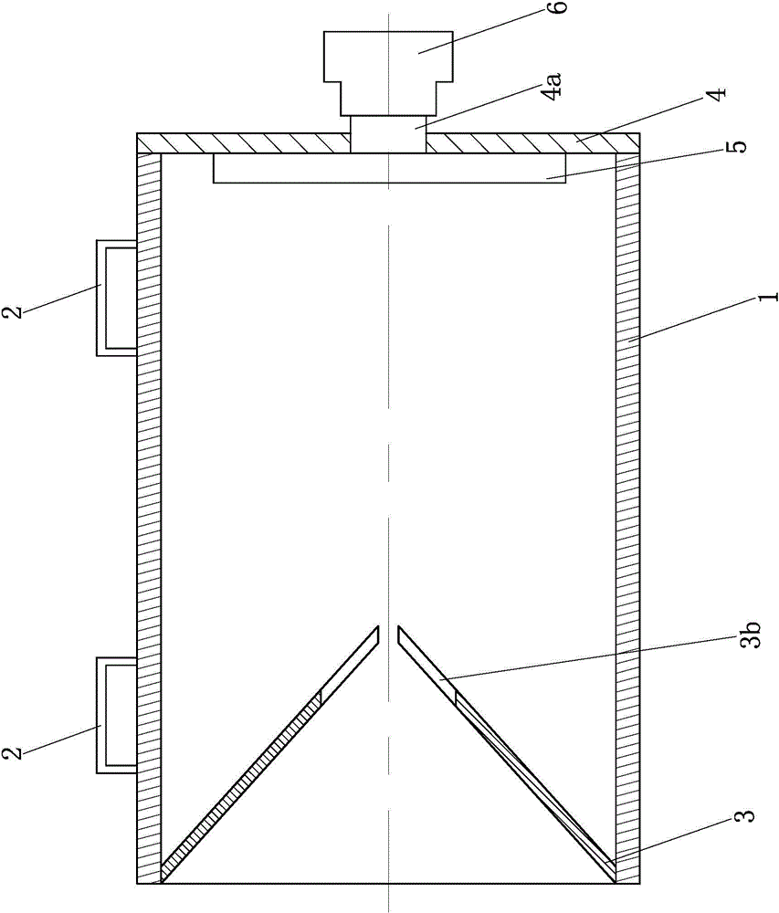
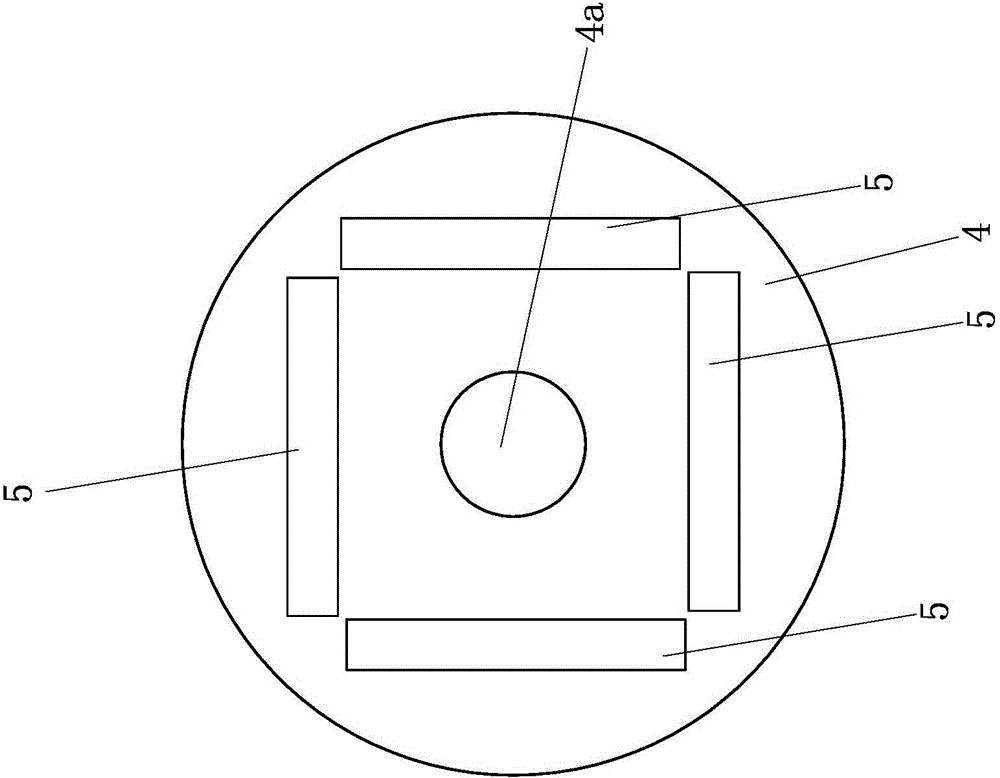
[0026] Such as figure 1 , 2 , shown in 3 and 4, a kind of desinsection device mainly is made of outer cylindrical body 1, fixture 2, conical anti-exit bucket 3, rear fixed plate 4, insect lamp 5 and pest collection bottle 6. Wherein, outer cylinder body 1 is black cylinder body, and it is opaque, and purpose is to prevent that the light that attracts insect lamp 5 sends from here, thereby avoids that pest gathers outside outer cylinder body 1, so just can't reach the purpose of killing pest. The upper part of the outer cylindrical surface of the outer cylinder 1 is fixed with a fixing device 2, the fixing device 2 is an "n"-shaped structure, and its number is two, and the two fixing devices 2 are respectively arranged at the front end of the outer cylinder 1 portion and rear end, the present invention can be firmly fixed on the fixed pole by these two fixtu...


PUM


Abstract

The invention discloses an insecticidal device, wherein a fixing device is arranged at the upper part of an external circular surface of an external barrel; a conical anti-back bucket with a big front part and a small back part is fixedly arranged in the front end opening of the external barrel; n axial shearing marks are uniformly arranged along the circumference of the back part of the conical anti-back bucket; a back fixed plate is fixedly arranged at the back end opening of the external barrel; a group of insect attracting lamps are fixedly arranged at the front plate face of the back fixed plate; fluorescent coating in each insect attracting lamp is arranged on the whole external circular surface of a corresponding lamp pole; an insect outlet is formed in the center of the back fixed plate; the back end of the insect outlet is in threaded connection with an insect collecting bottle. According to the insecticidal device disclosed by the invention, the structure of the insect attracting lamps is changed; the fluorescent coating is used for absorbing sunlight, and gives out light at night for attracting insects; the service life of the insect attracting lamps is quite long; the lamps do not need to be changed usually; electricity is not consumed; energy is saved; the manufacturing cost is low; furthermore, high voltage grids in traditional insecticidal lamps are not used, and the aims of collecting and killing the insects are also achieved, so that shortages caused by using the high voltage grids in the traditional insecticidal lamps are overcome.

Description

technical field [0001] The invention belongs to the field of agriculture and forestry, and relates to an insecticidal device for killing pests. Background technique [0002] As people pay more attention to ecological agriculture, more and more attention is paid to eliminating pests without using pesticides. Insecticidal lamps are a widely used device. Existing insecticidal lamps include a lamp cap and an insect collecting tray, and an insect-inducing lamp and a high-voltage electric grid are fixed between the two, wherein the insect-introducing lamp adopts a conventional LED lamp tube or a black light tube, and the insect-introducing lamp The high-voltage electric grid is arranged on the periphery, and the high-voltage electric grid always maintains a high-voltage state when it is powered. When in use, the light is emitted by the insect attracting lamp, and the phototaxis of the pest is used to attract the pest; when the pest touches the electric grid of the high-voltage el...

Claims


Application Information

Patent Timeline
Patent Type & Authority Applications(China)
IPC IPC(8): A01M1/04
Inventor 龚恒翔朱国军喻小华
Owner CHONGQING LIZHENYUAN AGRI & FORESTRY TECH
Why Eureka
Try Eureka