
Special powder conveying device for powder forming machine and work process of special powder conveying device

A technology of powder molding machine and powder feeding device, which is applied in the field of powder metallurgy, which can solve the problems of reducing the service life of products, insufficient local strength, and segregation of metal powder, etc., and achieve the effects of increasing service life, improving product quality, and less powder leakage during feeding

Inactive Publication Date: 2015-04-01
YANGZHOU HAILI PRECISION MACHINERY MFG
View PDF11 Cites 2 Cited by
  • Summary
  • Abstract
  • Description
  • Claims
  • Application Information

AI Technical Summary

Problems solved by technology

[0002] In powder metallurgy, it is generally necessary to set up a special powder feeding device to realize the powder feeding of the powder. During the powder feeding process of the existing powder feeding device, the hopper generally swings with the movement of the powder feeder. The metal powder segregates due to the swing, which affects the quality of the product. The density of each part of the product is not uniform, and the local strength is not enough, thereby reducing the service life of the product; needs further improvement

Method used


Image

  • Special powder conveying device for powder forming machine and work process of special powder conveying device
  • Special powder conveying device for powder forming machine and work process of special powder conveying device
  • Special powder conveying device for powder forming machine and work process of special powder conveying device

Examples


Embodiment Construction

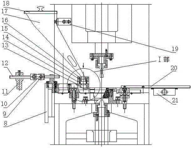
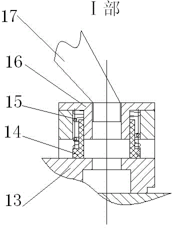
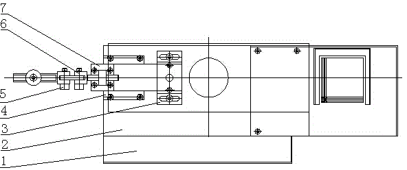
[0024] The powder material box 1 of the present invention includes a template 2, on which a powder feeder 13 that moves left and right along the template 2 is provided, and the powder feeder 13 is provided with a hopper 17 corresponding to the powder feeder 13; The hopper 17 is fixed, the upper part is provided with a hopper cover 18 corresponding to the hopper 17, and is fixed by the hopper bracket 19, the upper and lower parts of the powder feeder 13 are arranged, and the upper part of the powder feeder 13 can move up and down vertically , So that the upper surface of the upper part of the powder feeder 13 can be tightly abutted on the lower surface of the hopper 17.

[0025] The structure of the powder feeder 13 includes: a feeding fixing seat 3, a fixed guide tube 14, a guide plate 16 is sleeved in the guide tube 14, and the guide plate 16 is provided with a powder material hole; The upper part of the guide plate 16 forms an outer flanging, and a compression spring 15 is arra...


PUM


Abstract

The invention provides a special powder conveying device for a powder forming machine and a work process of the special powder conveying device. The special powder conveying device comprises a template (2), wherein a powder conveyor (13) which leftwards and rightwards moves along the template (2) is arranged on the template (2), a hopper (17) corresponding to the powder conveyor (13) is arranged on the powder conveyor (13), the hopper (17) is stationary, the upper part and the lower part of the powder conveyor (13) are in split arrangement, and the upper part of the powder conveyor (13) can realize vertical upward and downward movement, so that the upper surface of the upper part of the powder conveyor (13) can be tightly abutted against the first lower surface of the hopper (17). The special powder conveying device has the advantages that the hopper does not swing along with the moving of the powder conveyor, so that the characteristics of the metal powder maintain the stable state, the product quality is greatly improved, and further product quality influence caused by a metal powder segregation phenomenon due to forward and back vibration and swinging of the hopper of the original air cylinder compression material conveying mechanism is avoided.

Description

Technical field [0001] The invention relates to a special powder feeding device for a powder molding machine and its working process, and belongs to the technical field of powder metallurgy. Background technique [0002] In powder metallurgy, it is generally necessary to set up a special powder feeding device to realize powder feeding. In the powder feeding process of the existing powder feeding device, the hopper generally swings with the movement of the powder feeder. This method is easy to be caused by the hopper. The swing causes the metal powder to segregate, which affects the quality of the product. The density of each part of the product is uneven, and the local strength is insufficient, thereby reducing the service life of the product. At the same time, the powder material of this structure form is easy to leak powder and cause great waste. Needs further improvement. Summary of the invention [0003] In view of the above-mentioned defects, the present invention aims to pr...

Claims


Application Information

Patent Timeline
Patent Type & Authority Applications(China)
IPC IPC(8): B22F3/03
Inventor 陈万祥冯金玉潘学仁
Owner YANGZHOU HAILI PRECISION MACHINERY MFG
Learn More