
Multidirectional rotation working soldering tin machine capable of overturning jigs

A multi-directional, soldering machine technology, applied in manufacturing tools, metal processing, welding equipment, etc., can solve problems such as inconvenient operation, long soldering interval time, and large soldering limitations

Active Publication Date: 2015-04-01
DONGGUAN OKATA ELECTRONICS & TECH
View PDF7 Cites 37 Cited by
  • Summary
  • Abstract
  • Description
  • Claims
  • Application Information

AI Technical Summary

Problems solved by technology

[0002] All welding mechanisms can only adjust the welding direction at a single angle. The operation is very inconvenient and the flexibility is poor, which seriously limits the adjustment of the soldering direction, and the soldering is limited. When soldering, when a workpiece is soldered, it must wait for completion The soldering workpiece is unloaded, and then it has to wait for the new workpiece to be loaded, resulting in a long soldering work cycle and a long soldering interval, which seriously affects the soldering work progress, low work efficiency and high cost

Method used


Image

  • Multidirectional rotation working soldering tin machine capable of overturning jigs
  • Multidirectional rotation working soldering tin machine capable of overturning jigs
  • Multidirectional rotation working soldering tin machine capable of overturning jigs

Examples


Embodiment Construction

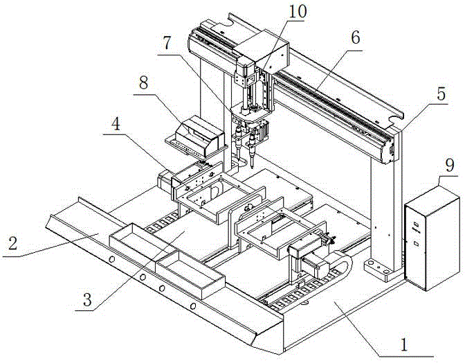
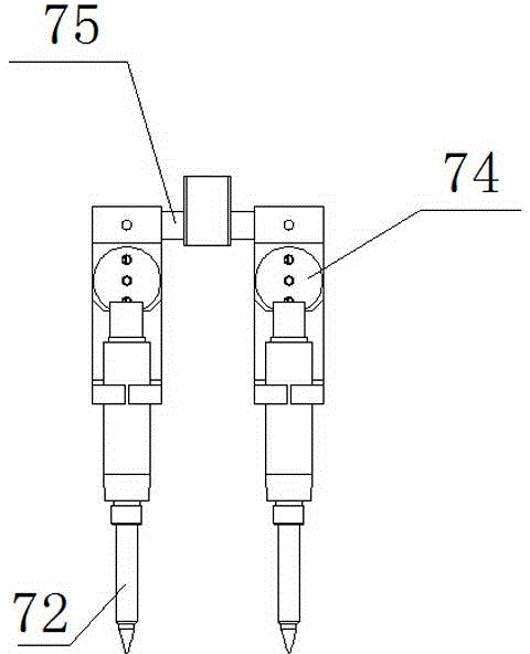
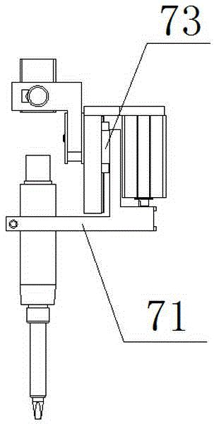
[0013] In this example, if Figure 1 to Figure 4 As shown, a reversible fixture multi-direction rotation work soldering machine of the present invention includes a machine panel 1, a material table 2 arranged in front of the machine panel 1, and a Y-axis transmission mechanism longitudinally arranged on the upper surface of the material table 2 3, and the turning mechanism 4 set on the Y-axis transmission mechanism 3 by sliding back and forth, and the welding bracket 5 set above the material table 2, and the X-axis transmission mechanism 6 set on the top of the welding bracket 5, and the X-axis transmission mechanism set on the X-axis In front of the mechanism 6, a multi-head independent control welding mechanism 7 that can slide left and right, and a tin slag box 8 that is arranged on the left end of the welding bracket 5 and is used to recycle the soldering iron by blowing tin or carry out tin cleaning treatment on the tip of the soldering iron, and is arranged on the welding...


PUM


Abstract

The invention relates to a multidirectional rotation working soldering tin machine capable of overturning jigs. The multidirectional rotation working soldering tin machine capable of overturning the jigs comprises a machine panel, a material station, Y-axis conveying mechanisms, overturning mechanisms, a welding bracket, an X-axis conveying mechanism, a multi-head independent control welding mechanism, a tin slag box, a welding station box, a soldering iron fixing block, a soldering iron, a sliding rail guide buffering assembly, a soldering iron left-and-right inclination angle regulating mechanism, a front-and-rear rotary regulating bracket and a soldering iron transfer cylinder. The multidirectional rotation working soldering tin machine capable of overturning the jigs can be used for determining to set the numbers of the overturning mechanisms and the Y-axis conveying mechanisms according to loading time and tin soldering time; by arranging more than one overturning mechanism paired with the Y-axis conveying mechanisms for use, a circuit board on which materials are loaded can be full-automatically overturned in a range of 180 degrees and the multi-head independent control welding mechanism can carry out non-stop tin soldering; the working efficiency is high; the working angle of the soldering iron in the random front-and-rear inclined direction can be regulated by the front-and-rear rotary regulating bracket; the working angle of the soldering iron in the random left-and-right inclined direction can be regulated by the soldering iron left-and-right inclination angle regulating mechanism; the multidirectional rotation working soldering tin machine capable of overturning the jigs has strong flexibility, has good effects and is low in cost.

Description

technical field [0001] The invention relates to a multi-direction rotation working soldering machine with reversible jigs. Background technique [0002] All welding mechanisms can only adjust the welding direction at a single angle. The operation is very inconvenient and the flexibility is poor, which seriously limits the adjustment of the soldering direction, and the soldering is limited. When soldering, when a workpiece is soldered, it must wait for completion The soldering workpiece is unloaded, and then the new workpiece has to be loaded, resulting in a long soldering work cycle and a long soldering interval, which seriously affects the soldering work progress, low work efficiency, and high cost. Therefore, in view of the shortcomings of the above-mentioned technical problems in the traditional welding mechanism, the applicant has developed a method that can determine the number of turning mechanisms and Y-axis transmission mechanisms according to the feeding time and so...

Claims


Application Information

Patent Timeline
Patent Type & Authority Applications(China)
IPC IPC(8): B23K3/00B23K3/08
CPCB23K3/00B23K3/027B23K3/029B23K3/047B23K3/08B23K3/087B23K2101/42
Inventor 吴水鱼
Owner DONGGUAN OKATA ELECTRONICS & TECH
Learn More