
Tool magazine door for machining center

A machining center and tool magazine technology, applied in the field of tool magazine doors, can solve the problems of not being completely sealed, affecting tool life and machining accuracy, etc., and achieving the effects of saving tool change time, good self-sealing, and simple structure

Active Publication Date: 2016-09-14
DALIAN SUNLIGHT TECH CO LTD
View PDF7 Cites 0 Cited by
  • Summary
  • Abstract
  • Description
  • Claims
  • Application Information

AI Technical Summary

Problems solved by technology

[0003] At present, the structure of the commonly used tool magazine door mainly includes several forms such as side pull, pull up and flip. When the cylinder and guide rail or linear guide rail are used for driving and guiding alone, due to the splash of coolant and iron filings in the process, It cannot be completely sealed, so that the coolant or fine iron filings seep into the tool magazine, which affects the life of the tool and the machining accuracy

Method used


Image

  • Tool magazine door for machining center
  • Tool magazine door for machining center
  • Tool magazine door for machining center

Examples


Embodiment Construction

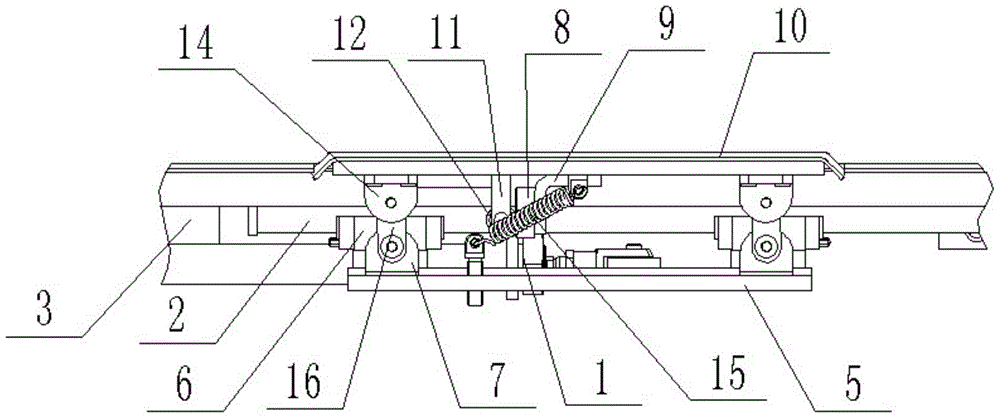
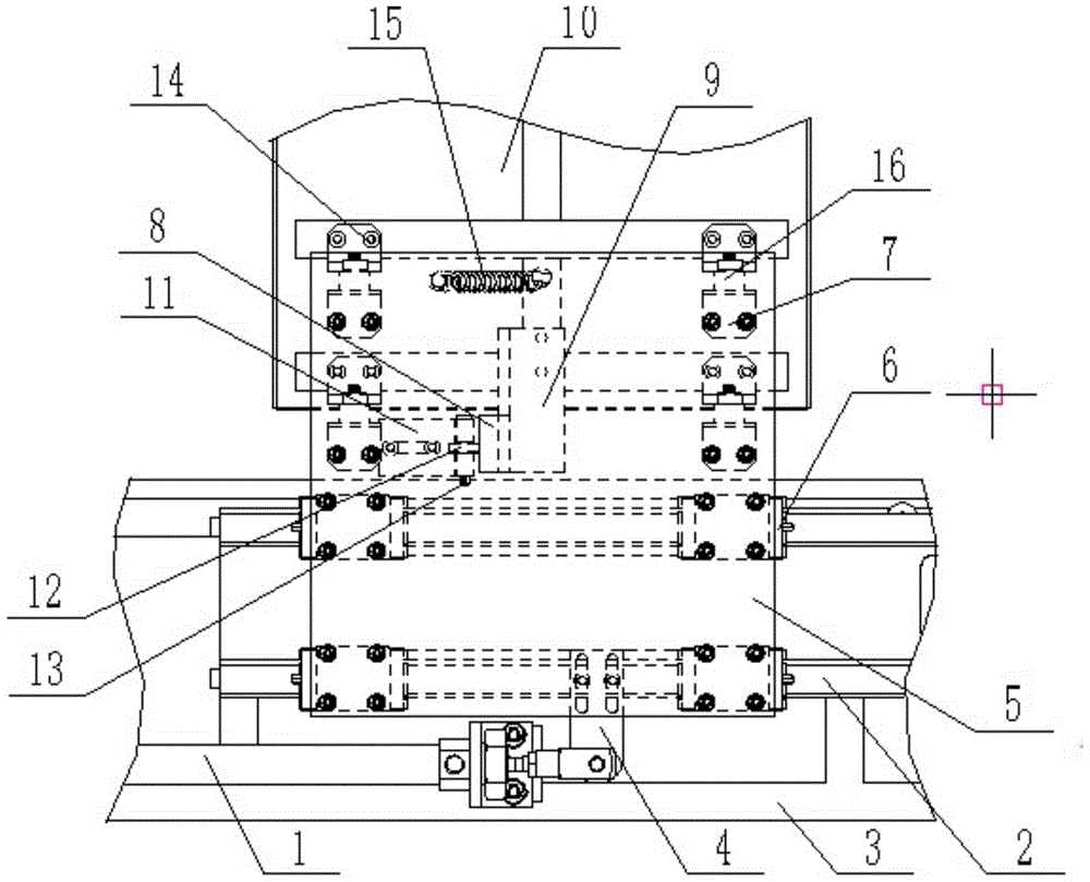
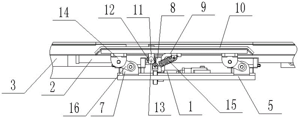
[0014] The present invention will be further described below in conjunction with accompanying drawing. figure 1 It is the front view when the tool magazine door of the machining center of the present invention is closed, figure 2 for figure 1 bottom view. The machining center uses the tool magazine door, the cylinder 1 and the guide rail 2 are fixed on the machine tool protection 3, the cylinder 1 is hinged to the connection plate 4, the connection plate 4 is fixed on the protection plate 5, and the protection plate 5 is fixed to the guide rail slide seat 6 and the lower end of the hinge 7 connection, the block 8 is fixed on the tool magazine door 10 by the support 9, the bearing support 11 is fixed on the machine tool protection 3, the bearing 12 is fixed on the bearing support 11 through the pin shaft 13, and the hinge upper end 14 is connected with the tool magazine door 10 Fixed, the hinge upper end 14 and the hinge lower end 7 are respectively hinged with the long plat...


PUM


Abstract

The invention discloses a tool changer door used for a machining center. A cylinder and guide rails are fixedly arranged on a machine tool guard; the cylinder and a connecting plate are hinged; the connecting plate is fixedly arranged on a prevention plate; the protection plate is fixedly connected with the lower ends of hinges and guide rail sliding seats; a stop dog is fixedly arranged on the tool changer door via a support; a bearing support is fixedly arranged on the machine tool guard; a bearing is fixedly arranged on the bearing support via a hinge pin; the upper ends of the hinges are fixed with the tool changer door; the upper ends of the hinges and the lower ends of the hinges are respectively hinged to long plates; one end of a spring is connected with the tool changer door, and the other end of the spring is connected with the protection plate. The left side and the right side of the tool changer door are provided with turnups at the angle of 45 degrees. The tool changer door used for the machining center has the advantages of simple structure, small noise and good self-sealing performance and is suitable for a small machining center with a limited space, and meanwhile, tool changing time is greatly shortened.

Description

technical field [0001] The invention relates to a tool magazine door, in particular to a tool magazine door for a machining center. Background technique [0002] The tool magazine door is a very critical part of the protection of the entire tool magazine system. It can be opened automatically when the spindle tool is changed, and it can prevent dust, water and iron filings after closing. [0003] At present, the structure of the commonly used tool magazine door mainly includes several forms such as side pull, pull up and flip. When the cylinder and guide rail or linear guide rail are used for driving and guiding alone, due to the splash of coolant and iron filings in the process, It cannot be completely sealed, so that the coolant or fine iron filings seep into the tool magazine, which affects the life and machining accuracy of the tool. Contents of the invention [0004] The technical problem solved by the present invention is to overcome the deficiencies of the prior ar...

Claims


Application Information

Patent Timeline
Patent Type & Authority Patents(China)
IPC IPC(8): B23Q1/01B23Q11/08
CPCB23Q3/155B23Q11/08
Inventor 俞洋王茂伟
Owner DALIAN SUNLIGHT TECH CO LTD
Learn More