3D printer head capable of feeding silk steadily

A technology of 3D printers and printing nozzles, which is applied in the field of 3D printing, can solve the problems of increased pressure of gears on wire materials, increased costs, and poor improvement effects, etc., and achieves the effect of reasonable structural design

Active Publication Date: 2015-04-01
ZHEJIANG IND & TRADE VACATIONAL COLLEGE
View PDF12 Cites 12 Cited by
  • Summary
  • Abstract
  • Description
  • Claims
  • Application Information

AI Technical Summary

Problems solved by technology

[0008]1. The structure of the improvement method is complicated and the cost increases
For example, the structure of the feeding device is more complicated after the spring is added; the structure of the double-hole nozzle increases the cost
[0009]2. The improvement effect is not good. For example, in the improvement of the wire feeding structure in CN203449611U and CN203611389U, the hard acute angle gear vertex on the wire feeding wheel is affected by the reaction of the spring Under the force, the contact area between the top corner of the gear and the wire material is very small, resulting in an increase in the pressure of the gear on the wire material
This will lead to uneven filament discharge from the nozzle
If the

Method used


Image

  • 3D printer head capable of feeding silk steadily
  • 3D printer head capable of feeding silk steadily
  • 3D printer head capable of feeding silk steadily

Examples


Embodiment 1

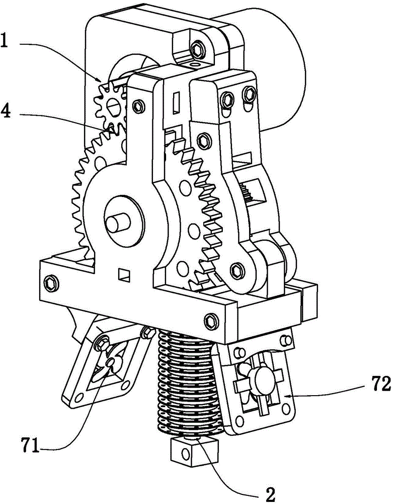
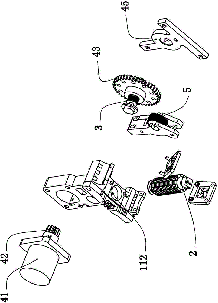
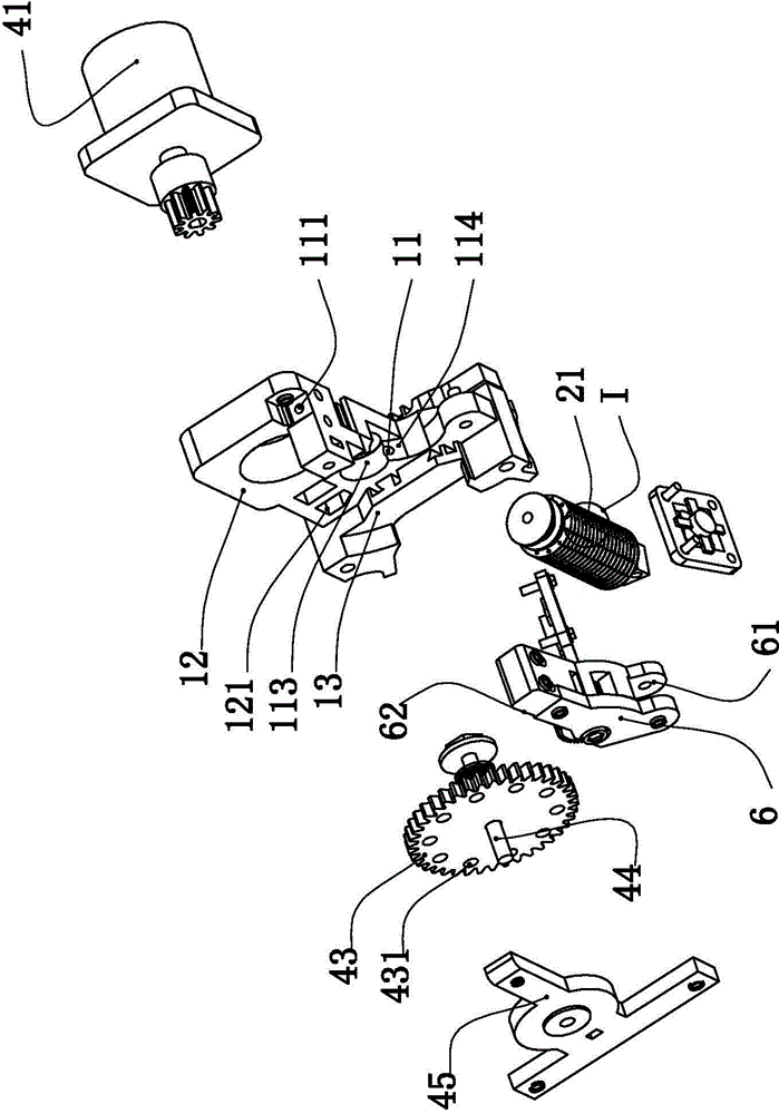
[0032] Such as Figure 1-5The specific embodiment of the present invention shown includes a base 1, and a feed channel 11 is arranged on the base, and one end of the feed channel is a feed end 111, and the other end is a discharge end 112. The discharge end 112 of the feeding channel is connected to the printing nozzle 2. The base 1 described in this embodiment includes a base upright bracket 12 and a base bottom plate 13 integrally fixed at the bottom of the base upright bracket. The print head 2 is disposed under the base plate 13 . In this embodiment, the lower end surface of the base bottom plate 13 is provided with a first heat dissipation fan 71 and a second heat dissipation fan 72 on both sides of the middle and lower section of the print nozzle 2, wherein the wind direction of the first heat dissipation fan 71 is blown from the outside to the print nozzle 2, The wind direction of the second heat dissipation fan 72 is blown from the print head 2 to the outside of the s...

Embodiment 2

[0039] Such as Image 6 , as shown in 7, the difference between Embodiment 2 and Embodiment 1 is that the circular elastic rubber ring gear 51 of Embodiment 2 is different from Embodiment 1, such as Image 6 , as shown in 7, the circular elastic rubber ring gear 51 in the present embodiment 2 has a plurality of pusher lobe teeth 511 distributed on the circumference of the rim, the outermost end of the pusher lobe is a pusher lobe 512, and The tooth profile on the pushing convex tooth 511, which is located on one side of the pushing lobe and is crimped with the wire material, is an arc-shaped tooth profile 5111, so that when the wire material is fed, the circular elastic rubber ring gear 51 follows the The wire material moves and rotates. During the rotation process, the arc-shaped tooth profile 5111 can ensure the stable crimping of the wire material, and with the process of rotation, the pushing force of the arc-shaped tooth profile 5111 on the wire material is in the pushing...


PUM


Abstract

The invention discloses a 3D printer head capable of feeding silk steadily; the 3D printer head comprises a base; a feeding channel is arranged on the base; a printing head is connected to the discharging end of the feeding channel; a U-shaped silk feeding wheel is rotatably arranged on the base corresponding to one side of the feeding channel; a silk feeding clamping wheel is rotatably arranged on the feeding channel corresponding to the other side of the U-shaped silk feeding wheel in a locating manner; a U-shaped elastic rubber gear ring matched with the wheel surface sleeves the wheel surface of the U-shaped silk feeding wheel; a circular elastic rubber gear ring sleeves the wheel surface of the silk feeding clamping wheel; a first crossed area exists between the periphery of the feeding channel and a U-shaped toothed groove; and the area of the first crossed area is in the deformation range of the U-shaped elastic rubber gear ring. The 3D printer head capable of feeding silk steadily disclosed by the invention is reasonable in structural design and capable of feeding silk steadily and reliably, and is beneficial to increasing FDM (Frequency-Division Multiplexing) printing efficiency and quality.

Description

technical field [0001] The invention belongs to the field of 3D printing, and specifically refers to a nozzle of a 3D printer with stable filament output. Background technique [0002] 3D printing technology appeared in the 1980s, also known as "rapid prototyping technology". Its biggest advantage is that any object can be directly generated from the graphic data designed by the computer without machining or grinding tools, thereby greatly shortening the product development cycle, improving productivity and reducing production costs. Therefore, it is widely used in art and industry. 3D printing technology, according to its different molding methods, can be divided into stereolithography (stcmolithography, SLA), laminated object manufacturing (Laminated Object Manufacturing, LOM), selective laser sintering (SelectiUe Laser Sintering, SLS), fused deposition manufacturing (Fused Deposition Modeling, FDM), etc. Among them, the most essential difference between the FDM rapid p...

Claims


Application Information

Patent Timeline
IPC IPC(8): B29C67/00
Inventor 关雷史子木陈庆喜
Owner ZHEJIANG IND & TRADE VACATIONAL COLLEGE
Why Eureka
Try Eureka