Sandwich energy-absorbing device

An energy-absorbing device and core-sandwich technology, applied in the field of energy-absorbing, can solve the problems of unsatisfactory energy-absorbing effect, inability to satisfy structural strength, stiffness, vibration resistance, impact resistance energy absorption performance, poor structural vibration resistance, etc. Achieve the effect of improving energy absorption capacity, improving anti-vibration capacity, and high specific strength

Inactive Publication Date: 2015-04-01
INST OF MECHANICS - CHINESE ACAD OF SCI
View PDF4 Cites 21 Cited by
  • Summary
  • Abstract
  • Description
  • Claims
  • Application Information

AI Technical Summary

Problems solved by technology

[0004] Traditional lattice sandwich panels and foam sandwich panels mainly absorb energy through the plastic deformation of panels and sandwich materials. Sandwich panels have certain strength and stiffness, but the overall energy absorption effect is not ideal
When the sandwich material is solid, the energy absorption effect is obviously improved, but the anti-vibration performance of the structure is poor.
Therefore, the existing sandwich panel structure cannot satisfy the structural strength, stiffness, vibration resistance, shock resistance and energy absorption performance at the same time.

Method used


Image

  • Sandwich energy-absorbing device
  • Sandwich energy-absorbing device
  • Sandwich energy-absorbing device

Examples


Embodiment 1

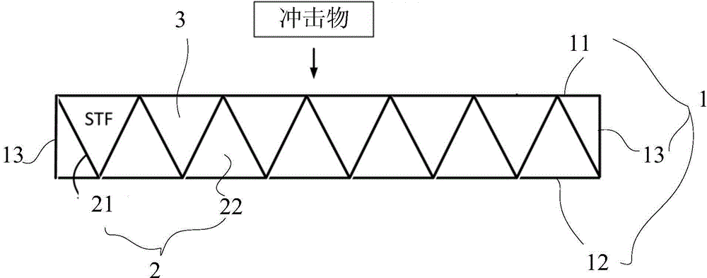
[0027] Such as figure 1 As shown, the embodiment of the present invention provides a sandwich energy-absorbing device, which includes a packaging panel 1 and a core layer 2 sealed in a closed space inside the packaging panel 1. The core layer 2 is composed of a core material 21 and filled in the core. material 21 and / or filled between the core material 21 and the closed space inside the packaging panel 1 formed by shear thickening fluid material 22; wherein the packaging panel 1 includes an upper panel 11, a lower panel 12, a side panel 13, a core panel The layer 2 is filled in the closed space formed by the upper panel 11, the lower panel 12, and the side panels 13. The core layer 2 includes a core material 21 and is filled between the core materials 21 and / or between the core material 21 and the Shear thickening fluid material 22 between the enclosed spaces.

[0028] The core material 21 in the present invention mainly forms a support skeleton for the core plate layer 2, an...

Embodiment 2

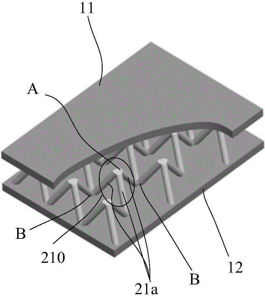
[0033] see figure 2 , the core material 21 is connected to each other by a plurality of first node units 210 to form a network; each first node unit 210 includes more than three (three in this embodiment, see figure 2 ) is a core material rod 21a arranged in a spatial shape, one end of the core material rod 21a is connected to the same node (the first node A), and the other end of the core material rod is connected to the node (the first node A) respectively. On a different node (the second node B) that is adjacent and opposite in direction; the node above (see figure 2 The first node A) in is connected to the upper panel 11, and the lower node (see figure 2 The second node B) in is connected to the lower panel 12 .

Embodiment 3

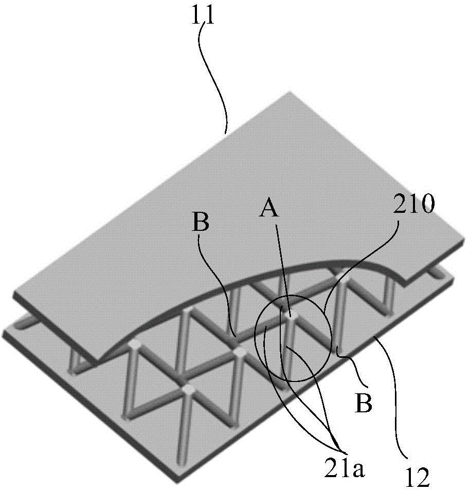
[0035] see image 3 The only difference between this embodiment and the second embodiment is that each first node unit 210 includes four core material rods 21a arranged in a spatial shape.


PUM


Abstract

The invention provides a sandwich energy-absorbing device which comprises an upper panel, a lower panel, lateral plates and a core plate layer, wherein the core plate layer is fed in a closed space formed by enclosing the upper panel, the lower panel and the lateral plates, and the core plate layer comprises core materials and a shear thickening fluid material fed between the core materials and/or fed between the core materials and the closed space. When an energy-absorbing device suffers from an action an external impact, structures of the upper panel, the lower panel, the lateral plates and the core materials rapidly deform, so that a quick shear action is applied to the shear thickening fluid material fed in a core plate, the viscosity of the shear thickening fluid material with a relatively high shear strain rate is rapidly improved, and thus impact energy is rapidly dissipated, and relatively high specific strength, specific stiffness and vibration resistance and energy absorption capabilities are achieved.

Description

technical field [0001] The invention relates to energy-absorbing technology, in particular to a sandwich energy-absorbing device. Background technique [0002] Space lattice sandwich energy-absorbing structure is an effective energy-absorbing structure that dissipates impact load energy through large plastic deformation. The sandwich structure is generally a porous metal structure. Compared with traditional single-layer panels, the panel sandwich structure has higher specific strength and specific stiffness, and also has functions such as shock absorption, temperature insulation, and sound absorption. The structural weight is reduced and the cost is reduced while meeting the mechanical performance requirements. The panel sandwich structure is usually used for the optimal design of lightweight structures, and has a large number of applications in engineering. [0003] Traditional lattice sandwich panels generally absorb energy through large plastic deformation of structura...

Claims


Application Information

Patent Timeline
Patent Type & Authority Applications(China)
IPC IPC(8): B32B3/12B32B1/06B32B5/18B32B33/00
CPCB32B3/12B32B3/08B32B5/18B32B33/00B32B2307/558B32B2307/56
Inventor 吴先前黄晨光
Owner INST OF MECHANICS - CHINESE ACAD OF SCI
Why Eureka
Try Eureka