

Composite type multi-mode multi-purpose aircraft
A multi-modal, aircraft technology, used in flight direction control, aircraft parts, aircraft control and other directions, can solve the problems of high mode conversion control difficulty, high engine requirements, complex mechanism, etc., to reduce cost and complexity, The effect of reducing waste and energy consumption and improving safety
Inactive Publication Date: 2015-04-01
BEIHANG UNIV
View PDF6 Cites 46 Cited by
- Summary
- Abstract
- Description
- Claims
- Application Information
AI Technical Summary
Problems solved by technology
[0028] The present invention proposes a composite multi-mode multi-purpose aircraft, which is a V/STOL aircraft based on the composite layout of propeller-tip jet drive/autorotating rotor/fixed wing, and the
Method used
View moreImage
Smart ImageViewing Examples

Examples
 PUM
 Abstract
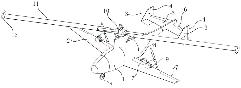
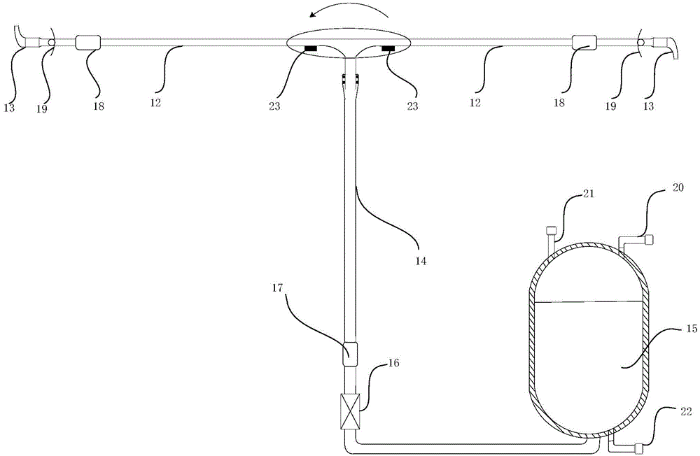
The invention discloses a composite type multi-mode multi-purpose aircraft, and belongs to the technical field of overall design of aviation flight vehicles. The aircraft comprises a body of a fixed wing aircraft, a driving/autorotation rotor wing system, an expelling aero-engine and a flying control system, wherein the driving/autorotation rotor wing system comprises paddle hubs and paddles; the paddles are hollow, and guide tubes B are communicated with the inner parts of the paddles; an H2O2 catalysis decomposition engine is mounted at the tail end of each paddle; the H2O2 catalysis decomposition engines are connected with the guide tubes; the guide tubes are communicated with guide tubes A; the guide tubes A are connected with an H2O2 storage box. The aircraft disclosed by the invention has the property of vertical/short-distance lifting and suspension, or even can achieve certain back flying and side flying, and can also fly forwards at a high speed; due to adoption of paddle tip air injection driving/autorotation wings, no reaction torque is generated in any mode, and thus a tail rotor as well as a speed reduction transmission and control mechanism of an ordinary helicopter are canceled; the differential thrust for thrusting an aero-engine is adopted to control to achieve steadiness and control in flying direction at a low speed, the waste weight and the energy consumption are reduced, the cost is lowered, the complexity is alleviated, and the flying security in a complex environment is effectively improved.
Description
technical field [0001] The invention relates to an aerodynamic layout and structure of a composite multi-mode vertical / short take-off and landing aircraft, specifically a composite vertical / short take-off and landing aircraft based on propeller-tip jet drive / autorotating rotor / fixed wing, belonging to In the technical field of general design of aviation vehicles, it is especially suitable for use in environments with harsh take-off and landing conditions such as ships, islands and reefs. Background technique [0002] In recent years, Vertical / Short Takeoff and Landing (V / STOL) aircraft has received extensive attention in both military and civilian fields due to its distinctive technical characteristics and excellent comprehensive performance. Typical representatives are American F35-B and tiltrotor V-22 "Osprey". This represents an important trend in the development of future aviation technology, that is, through the use of innovative composite layouts, the aircraft can sim...
Claims
Login to View More Application Information
Patent Timeline
 IPC IPC(8): B64C9/00B64C15/00
CPCY02T50/40
Inventor蔡志浩林清刘宁君闫坤王英勋
OwnerBEIHANG UNIV