Limiting sliding fixing device

A fixing device and limit slip technology, which is applied in the field of aerospace materials, can solve the problems of large deformation of the antenna array, excessive thermal stress, large bending or twisting of the antenna array, etc., and achieve the effect of increasing mechanical reliability

Inactive Publication Date: 2015-04-01
NAT SPACE SCI CENT CAS
View PDF5 Cites 3 Cited by
  • Summary
  • Abstract
  • Description
  • Claims
  • Application Information

AI Technical Summary

Problems solved by technology

After the analysis of the thermal deformation and thermal stress of the antenna array on rail, it is found that due to the fixation of the four outer screws, when the thermal deformation of the antenna array occurs on rail, the outer deformation of the antenna array is relatively large, resulting in a plate-shaped antenna array. The surface will be greatly bent or twisted, which will affect the electrical performance of the antenna surface, and the thermal stress may also exceed the reliable range of the antenna surface material

Method used


Image

  • Limiting sliding fixing device
  • Limiting sliding fixing device

Examples


Embodiment Construction

[0023] The present invention will be further described below in conjunction with the accompanying drawings and specific embodiments.

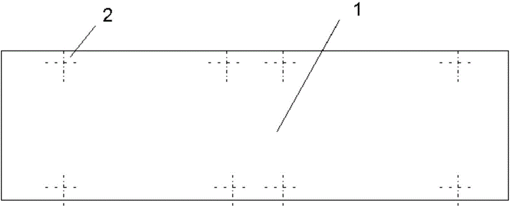
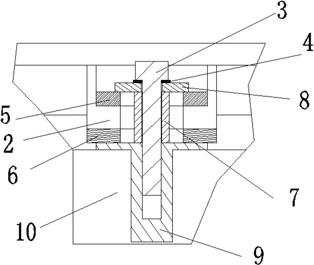
[0024] like figure 2 As shown, a limit slip fixing device is installed on the four mounting feet 2 outside the antenna front 1, and is used to fix the antenna front 1 on the bracket. The device includes: screws 3, screw washers 4. The first solid lubricating sheet 5, the second solid lubricating sheet 6, the sleeve 7, the transition gasket 8 and the embedded block 9; the first solid lubricating sheet 5 and the second solid lubricating sheet 6 pass through the countersunk head The screws are respectively fixed on the top and bottom of the mounting foot 2; the middle part of the first solid lubricating sheet 5, the second solid lubricating sheet 6 and the mounting angle 2 is provided with an oblong through hole of the same size for the sleeve 7 Inserted into the installation angle 2, the screw 3 is screwed into the threaded hole in the center o...


PUM


Abstract

The invention relates to a limiting sliding fixing device which is installed on four installation legs (2) at the outer side of an antenna array (1). The limiting sliding fixing device comprises screws (3), screw spacers (4), first solid lubricating plates (5), second solid lubricating plates (6), sleeves (7), transitional spacers (8) and embedded blocks (9); the first solid lubricating plates (5) and the second solid lubricating plates (6) are respectively fixed on and under the installation legs (2) through sunk screws; long circular through holes which are identical in size are respectively formed in the middle parts of the first solid lubricating plates (5), the second solid lubricating plates (6) and the installation legs (2) and used for the sleeves (7) to insert into the installation legs (2), and the screws (3) penetrates through the sleeves (7) to be tightened into threaded holes in the centers of the embedded blocks (9); the screw spacers (4) are arranged below the head parts of the screws (3), and the transitional spacers (8) are arranged between the screw spacers (4) and the first solid lubricating plates (5).

Description

technical field [0001] The invention relates to the field of aerospace materials, in particular to a limiting slip fixing device. Background technique [0002] The new aerospace antenna array is a rectangular plate structure (such as figure 1 shown), using the traditional way of direct screw fixation, which is fixed on the composite material bracket by eight screws. After the analysis of the thermal deformation and thermal stress of the antenna array on rail, it is found that due to the fixation of the four outer screws, when the thermal deformation of the antenna array occurs on rail, the outer deformation of the antenna array is relatively large, resulting in a plate-shaped antenna array. The surface will be greatly bent or twisted, which will affect the electrical performance of the antenna surface, and the thermal stress may also exceed the reliable range of the antenna surface material. Contents of the invention [0003] The purpose of the present invention is to ov...

Claims


Application Information

Patent Timeline
Patent Type & Authority Applications(China)
IPC IPC(8): B64G1/66
Inventor 栗晓鹏陈博范文杰
Owner NAT SPACE SCI CENT CAS
Why Eureka
Try Eureka