
Elevator bucket conveyor test device and method

A test device and feeder technology, applied in the direction of conveyor control device, conveyor, conveyor objects, etc., can solve the problems of low accuracy of solid flowmeter, difficult to achieve the purpose of the test, large error, etc., to achieve extended trouble-free Working time, optimized design, the effect of improving conveying performance

Active Publication Date: 2015-04-01
YANGTZE UNIVERSITY
View PDF7 Cites 7 Cited by
  • Summary
  • Abstract
  • Description
  • Claims
  • Application Information

AI Technical Summary

Problems solved by technology

[0004] Chinese patent document CN 102419257 A discloses a sand delivery test device for a fracturing sand mixing vehicle, which records a circulating sand delivery device that uses a solid flow meter to measure the instantaneous flow and cumulative flow. The problem is that the solid flow meter The accuracy is too low, the error is large, the total error reaches 5%~10%, it is difficult to achieve the purpose of the test

Method used


Image

  • Elevator bucket conveyor test device and method
  • Elevator bucket conveyor test device and method
  • Elevator bucket conveyor test device and method

Examples


Embodiment 1

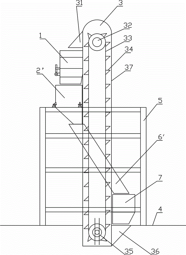
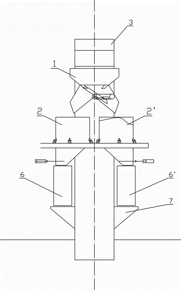
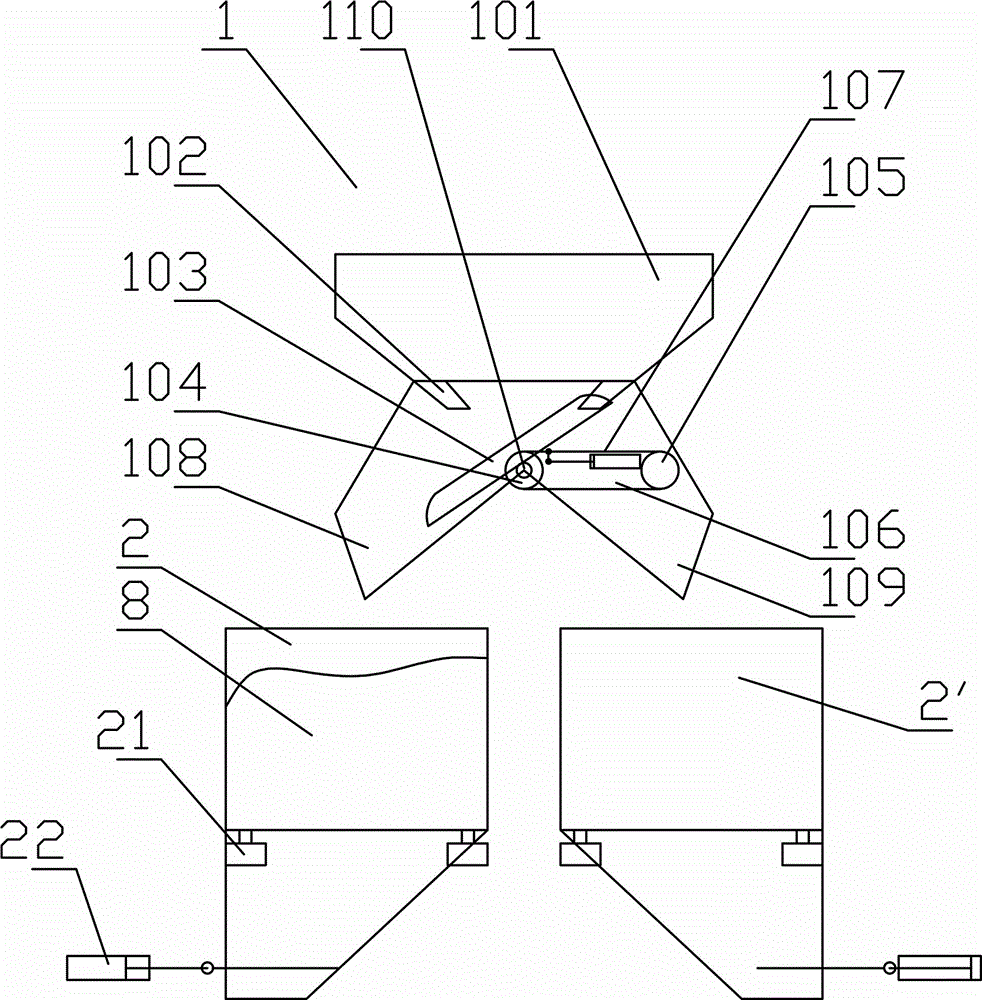
[0034] Such as Figure 1~5 Among them, a lifting bucket conveyor test device, a flow diversion device 1 is provided below the discharge port 31 of the lifting bucket conveyor 3, and the bottom of the flow separation device 1 is provided with a switchable first discharge port 108 and a second discharge port. port 109, a first weighing hopper 2 is provided below the first discharge port 108, and a second weighing hopper 2' is provided below the second discharge port 109;

[0035] The bottom of the first weighing hopper 2 is provided with a first circulation chute 6, the bottom of the second weighing hopper 2' is provided with a second circulation chute 6', and the bottom of the first circulation chute 6 and the second circulation chute 6' is provided with a storage tank. The hopper 7 and the storage hopper 7 are located above the feeding port 36 of the lifting bucket conveyor 3 .

[0036] preferred as Figure 2~4 Among them, the first weighing hopper 2 and the second weighing ...

Embodiment 2

[0049] On the basis of Example 1, such as figure 1 , 2 , 6. A method for carrying out a material delivery test using the above-mentioned lifting bucket conveyor test device, comprising the following steps:

[0050] 1. Switch the diverter device 1 to the first discharge port 108, and close the gate of the first weighing hopper 2, as image 3 shown in .

[0051] 2. The storage hopper 7 supplies material to the feeding port 36 of the lifting bucket conveyor 3, and the frequency conversion motor or hydraulic motor on the lifting bucket conveyor 3 starts feeding, and the start time t is set 0 , the material is discharged from the discharge port 31 of the lifting bucket conveyor 3 to the distribution device 1, and is discharged into the first weighing hopper 2 through the first discharge port 108, and the load cell 21 starts weighing; Before the sensor 21 is set, the weight including the entire first weighing hopper assembly is set to zero. This is convenient for later calculati...


PUM


Abstract

The invention relates to an elevator bucket conveyor test device and method. A distribution device is arranged under a discharge opening of an elevator bucket conveyor, a first discharge outlet and a second discharge outlet which are switchable are arranged in the bottom of the distribution device, and a first weighing hopper and a second weighing hopper are arranged under the discharge outlets respectively. Two circulatory chutes are arranged below the weighing hoppers respectively, a storage hopper is arranged under each circulatory chute, and each storage hopper is located over a feed opening of the elevator bucket conveyor. The elevator bucket conveyor test method includes switching the distribution device to the first discharge outlet or the second discharge outlet circularly, and acquiring accurate material weight by means of static weighing so as to obtain average flow rate within a period of time. By the aid of the circulatory static weighing method, high-precision instantaneous flow rate of material conveying and accumulated flow rate can be obtained. Therefore, the elevator bucket conveyor can be subjected to optimization design according to test data, conveying performance is improved, and time between failures is prolonged. The test device and the test method can be used for carrying out calibration test of the conveying performance before delivery.

Description

technical field [0001] The invention relates to the field of conveying test devices, in particular to a test device and method for a lifting bucket conveyor. Background technique [0002] Elevating bucket conveyor is a very widely used conveying equipment, also known as bucket elevator. Lifting bucket conveyors can be divided into: belt type bucket elevator (DT), chain type bucket elevator (TH) and plate chain type elevator (NE) according to the structure. Belt-type bucket elevator is suitable for conveying normal temperature powder, such as dry powder mortar, dry-mixed mortar, thermal insulation mortar, ready-mixed mortar, admixture, joint agent, interface agent, putty powder, chemical fine powder, economical and practical, the disadvantage is that the belt It is easy to go off track and needs frequent adjustments. Plate chain and ring chain bucket elevators adopt single-row or double-row chains, which are suitable for vertically conveying powdery, granular and small lump...

Claims


Application Information

Patent Timeline
Patent Type & Authority Applications(China)
IPC IPC(8): B65G43/08B65G17/12
CPCB65G17/126B65G43/08
Inventor 周思柱贾宏禹李宁袁新梅曾运运
Owner YANGTZE UNIVERSITY
Learn More