A liquid nitrogen pump truck

A liquid nitrogen pump and liquid nitrogen technology, applied in the direction of pumps, piston pumps, pump devices, etc., can solve the problems of nitrogen waste, difficulty in model selection, difficulty in satisfying liquid nitrogen pump trucks, etc., and achieve the effect of increasing coverage

Active Publication Date: 2016-08-31
SANY PETROLEUM INTELLIGENT EQUIP CO LTD
View PDF9 Cites 0 Cited by
  • Summary
  • Abstract
  • Description
  • Claims
  • Application Information

AI Technical Summary

Problems solved by technology

[0004] At present, due to the increasing nitrogen displacement and pressure required for construction, higher requirements are put forward for the performance of liquid nitrogen pump trucks in all aspects. However, it is increasingly difficult for existing liquid nitrogen pump trucks to meet this requirement.
For example, in the existing liquid nitrogen pump truck, the cost of the engine, high-pressure plunger pump and transmission system components, especially the transmission box, is relatively high. The required cost will rise rapidly, and the type selection is difficult, so it is difficult to be widely used; moreover, the transmission box of the existing liquid nitrogen pump truck is step-variable, which makes the displacement of the liquid nitrogen pump truck discontinuous. In order to meet the construction needs, In most cases, the displacement of the liquid nitrogen pump truck is greater than the displacement required for construction, which causes a huge waste of nitrogen; in addition, the structure of the high-pressure plunger pump is complicated and takes up space, which is not conducive to internal repair and maintenance, and also It is not conducive to external repair and maintenance and affects the arrangement of other parts on the car body

Method used


Image

  • A liquid nitrogen pump truck
  • A liquid nitrogen pump truck

Examples


Embodiment Construction

[0042] It should be pointed out that the description and sequence of specific structures in this section are only descriptions of specific embodiments, and should not be considered as limiting the protection scope of the present invention. In addition, the embodiments in this section and the features in the embodiments can be combined with each other under the condition of no conflict.

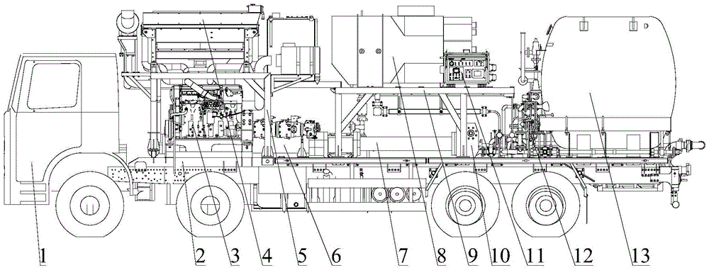
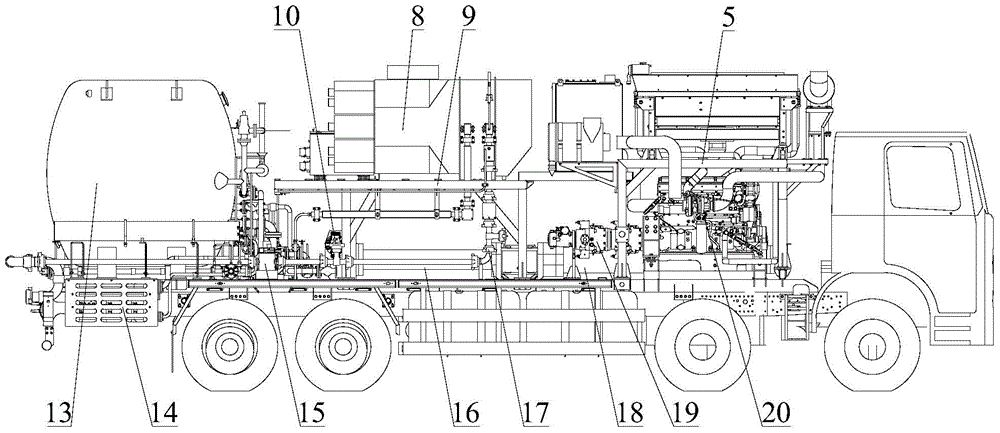
[0043] Please also refer to figure 1 and figure 2 , the liquid nitrogen pump truck of the embodiment of the present invention will be described in detail below in conjunction with the accompanying drawings.

[0044] As shown in the figure, the liquid nitrogen pump vehicle of this embodiment may include a chassis 1, a first engine 3, a second engine 20, a first hydraulic cylinder 6, a first plunger cylinder 7, a second hydraulic cylinder 18, a second cylinder Plug cylinder 16, low pressure manifold 12, high pressure manifold, multiple (two or more) hydraulic pumps 19, evaporator 8 and liquid...


PUM


Abstract

The invention relates to the technical field of nitrogen operations and discloses a liquid nitrogen pump truck. According to the liquid nitrogen pump truck, a first engine is used for driving at least one hydraulic pump; a second engine is used for driving other hydraulic pumps; the hydraulic pumps are used for providing pressure oil for a first hydraulic cylinder and a second hydraulic cylinder; the piston rod extension ends of the first hydraulic cylinder and the second hydraulic cylinder are respectively and movably arranged in a first plunger type cylinder and a second plunger type cylinder by virtue of plungers; and rodless cavities of the first plunger type cylinder and the second plunger type cylinder are respectively connected to an outlet of a low-pressure manifold and an inlet of a liquid nitrogen high-pressure manifold by virtue of a suction valve and an exhaust valve. According to the liquid nitrogen pump truck disclosed by the invention, the overall cost can be effectively reduced when the requirement on output power is met, infinitely variable transmission is realized, and the coverage range of the liquid nitrogen displacement and pressure is widened, so that the overall structure is compact, and the maintenance convenience is improved.

Description

technical field [0001] The invention relates to the technical field of nitrogen operation, in particular to a liquid nitrogen pump truck. Background technique [0002] The use of nitrogen to treat oil wells and oil layers is safe, time-saving, fast, and efficient, and has a high success rate. It is not only suitable for conventional oil reservoirs, but also has unique effects in special oil and gas reservoirs such as low pressure, low permeability, and clay cementation. Based on the characteristics of low density, good stability and easy compression of nitrogen, it has a wide range of applications in enhanced oil recovery, drilling, perforation, stimulation measures and workover, such as nitrogen gas lift, nitrogen replacement, mixed gas fracturing , mixed gas acidification, nitrogen positive and negative pressure perforation, nitrogen cushion test, etc. In terms of natural gas exploitation, nitrogen fracturing technology has a remarkable effect in natural gas exploitation ...

Claims


Application Information

Patent Timeline
Patent Type & Authority Patents(China)
IPC IPC(8): F17C7/04F02B63/06F04B9/10F04B23/06
Inventor 王从永王安伟闫大伟
Owner SANY PETROLEUM INTELLIGENT EQUIP CO LTD
Why Eureka
Try Eureka